TL;DR
Complete guide to building a privacy-focused home network with OPNsense. All traffic routes through VPN with automatic failover - no DNS or IP leaks to your ISP.
Prerequisites:
- Lenovo M920q (or similar) with Intel i350-T4 NIC
- Managed switch for VLAN support
- Basic networking knowledge
- Mullvad VPN subscription
What you’ll set up:
- Multi-VLAN network segmentation
- Redundant WireGuard VPN tunnels with failover
- AdGuard DNS filtering with kill switch
- DMZ isolation on dedicated interface
- Comprehensive firewall rules
Introduction
After years of using pfSense I finally got around to replacing it with OPNsense. While I’m at it, I also wanted to ‘improve/complicate’ the setup compared to what I had with pfSense.
Motivation was simple, get rid of pfSense and Netgear. Additionally, I wanted to improve security, privacy and maintainability while achieving my stated requirements. Most of these requirements had to be replicated from what I already had on pfSense using options available on OPNsense. (e.g. AdGuard vs pfBlockerNG)
This guide serves as documentation for my future self while helping fellow HomeLabers, Techies and anyone who wants to get back some digital privacy. Hopefully this can help you replicate something similar for your own use case.
Some specific parts, e.g. testing or setting up VLANs on Network Switches and WiFi APs will be in separate posts. This post primarily focuses on OPNsense and requires additional configuration on network switches.
This blog uses Mullvad as VPN provider because there is no better alternative. The instructions here focus on Mullvad only but you can easily replace it with a VPN provider of your choice that supports WireGuard.
Before we start, I want to do a shoutout to Schnerring whose guide + OPNsense docs made migrating to OPNsense a breeze. His guide inspired me to make some decisions to my OPNsense setup that I did not have with pfSense before.
Without further BS, let’s get into it.
Requirements
I had very specific goals, so please make necessary changes depending on your setup. Do not blindly copy what’s here.
Network Architecture Goals

VLAN Structure
The network is segmented into multiple VLANs, each serving a specific purpose with appropriate security controls:
| VLAN | Name | Purpose |
|---|---|---|
| LAN | Main Network | Secure LAN network for “trusted” devices |
| VLAN10 | DMZ | DMZ for public-facing server running various services, apps and tools |
| VLAN40 | SecWiFi | Secure WiFi network - extension to LAN but for wireless connections |
| VLAN42 | IoT | Separate VLAN for untrusted IoT devices |
| VLAN44 | Guest | Isolated VLAN for all guest devices (untrusted) |
| VLAN46 | GoatNET | Special purpose network (see below) |
| VLAN90 | Placeholder | Currently not used |
My wife works in marketing, tracking and analytics (AKA Dark side). She’s unable to do her job on LAN or VLAN40 (SecWiFi) due to anti-tracking and blocking measures that exist there. For her special case, I created dedicated VLAN46 which does not have any blocking in place. This network still gets routed through VPN, but she can work without my security measures getting in the way. In the end, happy wife = happy life.
Since I am using Mullvad DNS as upstream servers which come with filtering that VLAN46 (GoatNET) does not want. This requires a NAT rule that redirects DNS directly to 1.1.1.1 bypassing our AdGuard and Unbound. This is required for specific services that get filtered by Mullvad, for example google services such as ads.google.com or analytics.google.com.
If you choose to use 1.1.1.1 instead of Mullvad DNS e.g. 100.64.0.1 as upstream servers for Unbound, then the NAT redirect would go to Unbound on port 5353 instead.
Core Requirements
Beyond the VLAN structure, the network must meet these essential requirements:
Connectivity & Routing:
- Redundant VPN tunnel to the internet (primary with automatic failover to secondary)
- IPv4 Only (IPv6 disabled)
- All traffic routed through the 2 VPN tunnels with priority failover
- Port forwarding for services such as Proxies, Cloud services, Plex, and any other self-hosted application
Sometimes VPN provider servers go down, for example maintenance, in such cases we want to retain access to internet.
Making your internet access dependent on a single tunnel will create problems, that’s why I do not recommend trying this setup with a single tunnel.
DNS & Security:
- AdGuard DNS blocking for all networks (with
VLAN46exception) - Unbound Forwarding DNS Queries to Mullvad DNS servers
VLAN46traffic routed through VPNs but without AdGuardVLAN46has no DNS filtering and goes directly to1.1.1.1(bypass Mullvad DNS)- Quantum-secure VPN tunnel (Thanks Mullvad - not sponsored)
- Priority on real Open Source tooling and solutions
- DMZ for public-facing server with various services
Nothing leaves through WAN without VPN tunnel. This means:
- No information leaks to ISP
- No DNS leaks
- No WebRTC leaks
- Exception: Services like Plex that require direct connectivity
The goal is complete privacy - your ISP should see only encrypted VPN traffic.
DNS Architecture
The DNS setup uses three services working together: AdGuard filters queries, DNSmasq handles local domains, and Unbound forwards to Mullvad DNS through the VPN tunnel.
Important: Install AdGuard First
Since we are modifying default DNS & traffic flow, I highly recommend that you install AdGuard before following this guide. Installing it mid-setup while DNS is being reconfigured can cause temporary DNS resolution failures.
You don’t need to enable it until later, but installing it early prevents DNS resolution issues when downloading the AdGuard repository configuration later.
DNS Query Flow
graph TD
    Client[All Client Networks
    LAN, DMZ, SecWiFi, IoT, Guest, GoatNET]

    Client -->|Port 53| Router{NAT Redirect Rule}

    Router -->|DNS_ADGUARD_IG
    LAN, DMZ, SecWiFi
    IoT, Guest| AdGuard[AdGuard Home :53
    DNS Filtering]
    Router -->|NO_ADGUARD_IG
    GoatNET VLAN46| CF[Cloudflare 1.1.1.1
    via VPN]

    AdGuard -->|Local Domains| DNSmasq[DNSmasq :5335
    Local Resolution]
    AdGuard -->|All Other Queries| Unbound[Unbound :5353
    Upstream Resolver]

    Unbound -->|All Queries
    via VPN| Mullvad[Mullvad DNS
    100.64.0.X]

    CF -.->|Response| Client
    Mullvad -.->|Response| Unbound
    Unbound -.->|Response| AdGuard
    DNSmasq -.->|Response| AdGuard
    AdGuard -.->|Response| Client
Understanding the Flow
AdGuard receives all DNS queries on port 53 (DNS) and uses conditional forwarding to route them. Local domains home.byteron.com and reverse DNS for 10.x.x.x go to DNSmasq on port 5335. Everything else goes to Unbound on port 5353, which forwards through the VPN tunnel to Mullvad DNS.
VLAN46 (GoatNET) has a NAT redirect rule that sends DNS queries directly to Cloudflare
1.1.1.1, bypassing both AdGuard and Mullvad DNS filtering. However, this traffic still routes
through the VPN tunnel. Only the DNS resolver changes, not the routing path. This provides the
unfiltered DNS needed for marketing/analytics work while maintaining VPN privacy.
AdGuard Upstream DNS Configuration
The bracket syntax [/domain/]server:port creates conditional forwarding rules in AdGuard. Lines without brackets define the default upstream server.
[/home.byteron.com/]10.0.0.1:5335    # Local domain → DNSmasq
[/10.in-addr.arpa/]10.0.0.1:5335     # Reverse DNS → DNSmasq
10.0.0.1:5353                        # Everything else → Unbound
DNS services & Ports
| Service | Port | Purpose |
|---|---|---|
| AdGuard | 53 | DNS filtering and query routing |
| DNSmasq | 5335 | Local domain resolution and DHCP |
| Unbound | 5353 | Upstream resolver to Mullvad DNS |
Security outcome: Internal DNS structure never leaks outside your network, all external queries travel through encrypted VPN tunnels, and AdGuard filtering protects all networks except VLAN46 (which bypasses AdGuard for work requirements).
Additional Security Tools
Beyond the core setup, these tools can further enhance your network security:
| Tool | Purpose |
|---|---|
| Zenarmor | Next-generation firewall features and application control |
| CrowdSec | Collaborative security engine for threat detection and response |
| Suricata IPS/IDS | Intrusion Prevention and Detection System |
| Wazuh | Security Information and Event Management (SIEM) |
I’ll cover the setup and configuration of these tools in separate guides.
Hardware
Hardware selection was somewhat of a headache depending on the levels of risk you were willing to accept.
If nation states, hardware backdoors, etc are a concern for you, then you are pretty much out of affordable options.
Power consumption, noise and costs were some of my priorities when deciding the hardware. My old pfSense was running on a second-hand Dell OptiPlex 3080 with an i340-T4 Quad Port NIC. It was old and noisy and got quite hot by today’s standards. It’s been chugging along for many years and already ROIed 2-3 times over. I think it earned its retirement or a new role maybe? Nothing planned for now.
After comparing various options from AliExpress, local EU market and official devices from OPNsense the choices were narrowed down to a small form factor PC. Either a newer Dell OptiPlex or something from Lenovo ThinkCentre series.
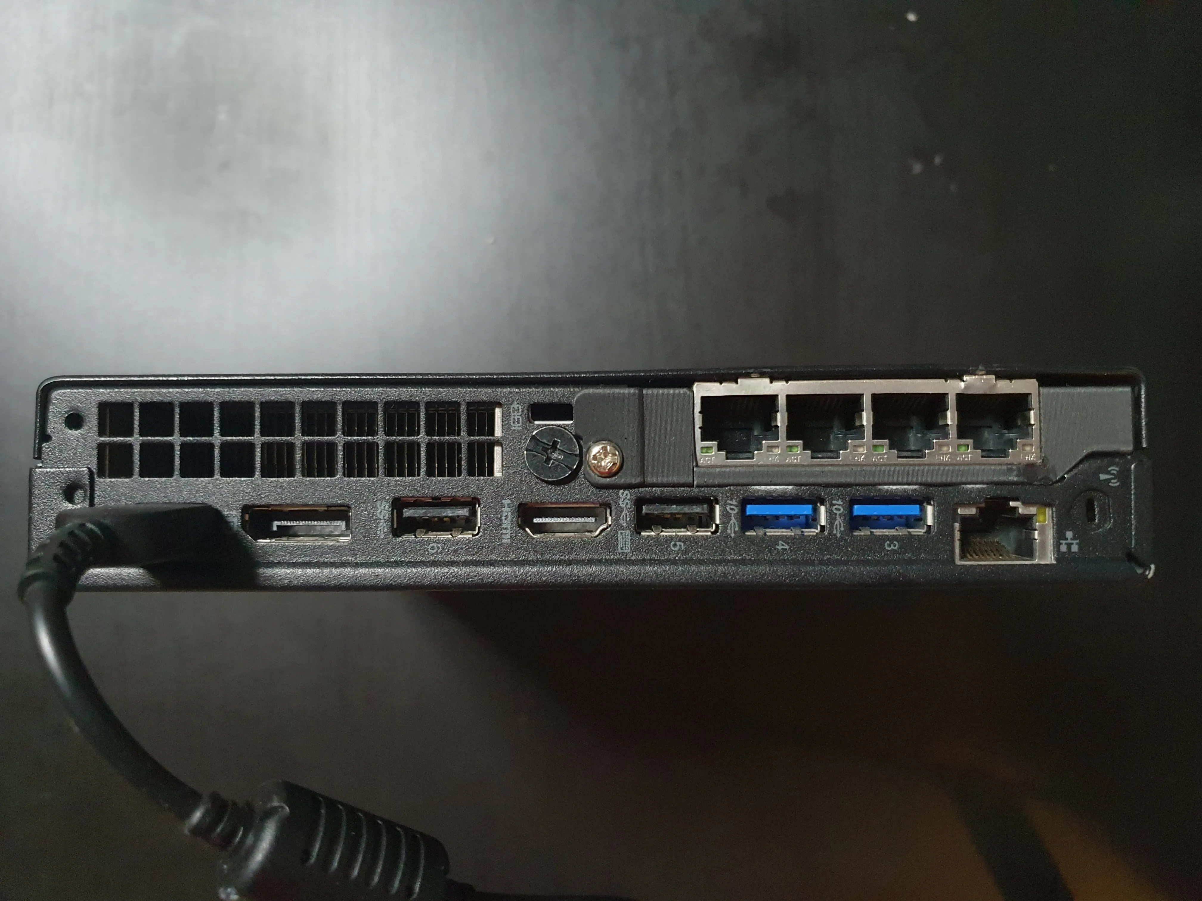
In the end I went for Lenovo M920q with an i350-T4 Quad Port NIC and a riser card. The total costs were under 230 euros, compared to DEC677 from OPNsense which is around 549, we are achieving similar or better performance for half the price.
That sounds like a good value proposition, no wonder so many people have done this exact path.
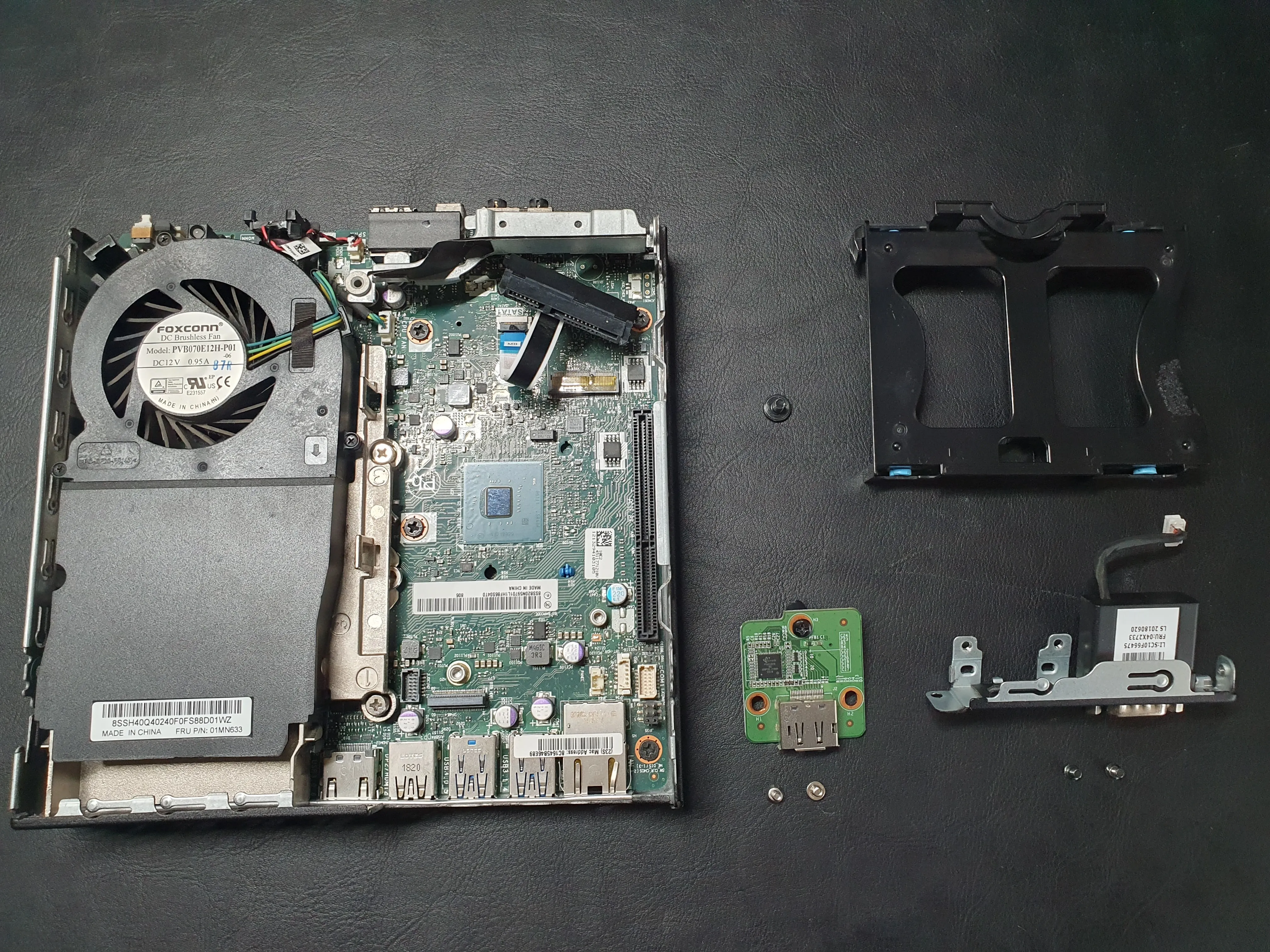
Here are some pictures of me taking it apart, installing the riser and i350-T4 NIC. I also 3D-printed a backplate cover from Makerworld which snapped immediately as I took it off the print plate. I did some soldering magic and fixed the break, installed the shield and we have our little box ready.
Images: Hardware Preparation
Below are some pictures I took while prepping the hardware
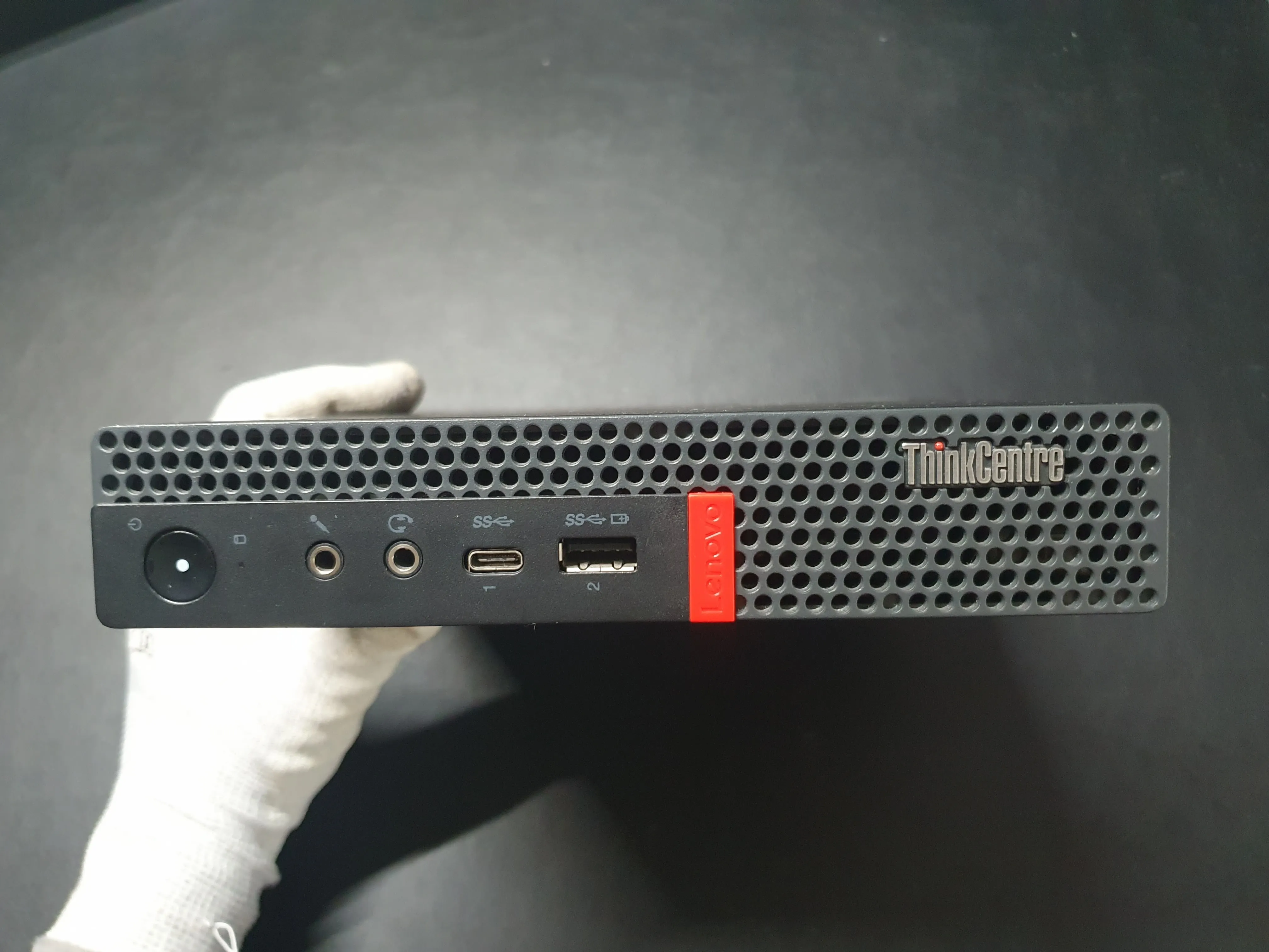
Removing unnecessary parts:
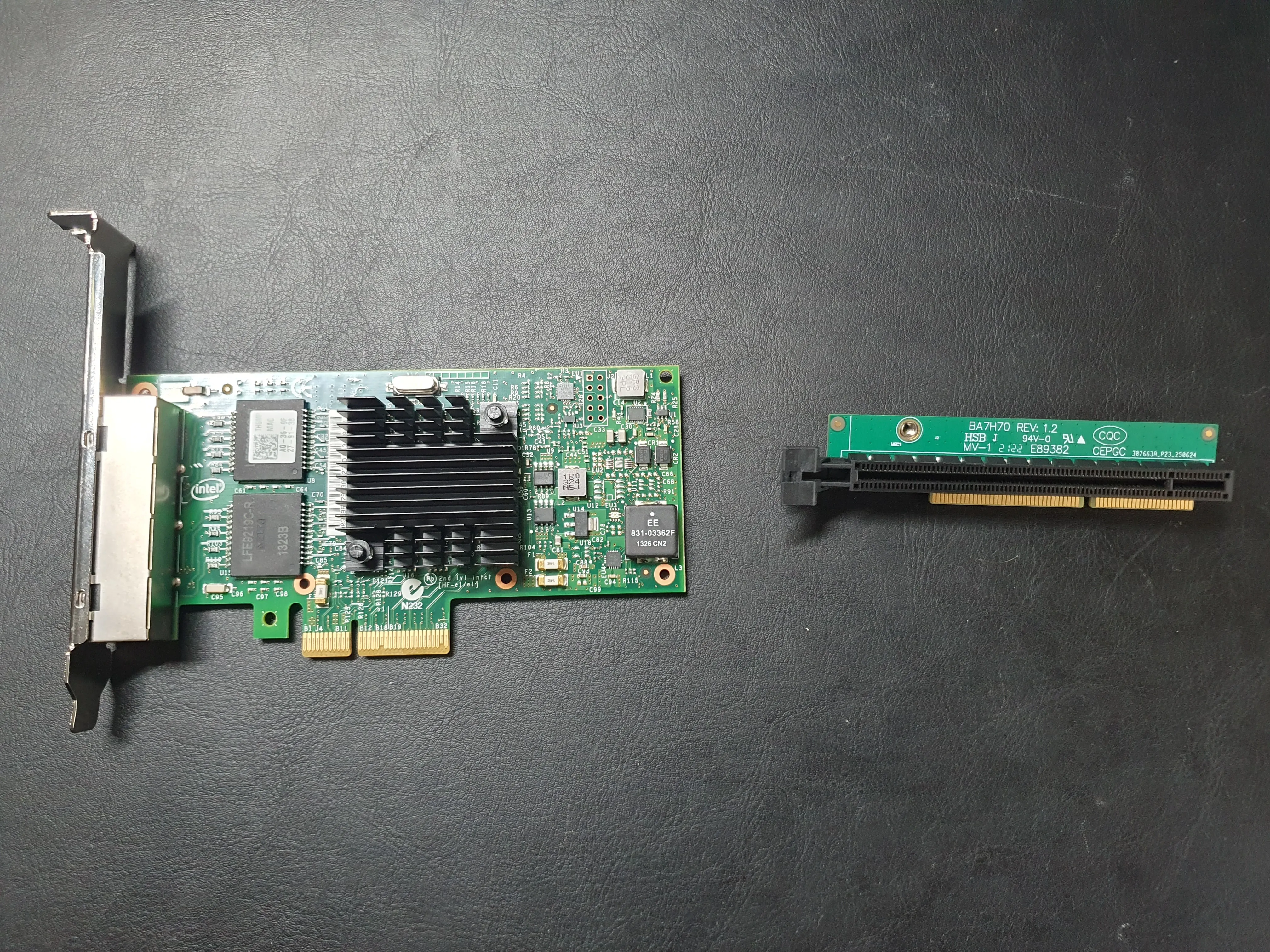
Intel i350-T4 and Riser card:
Placing NIC inside the riser:
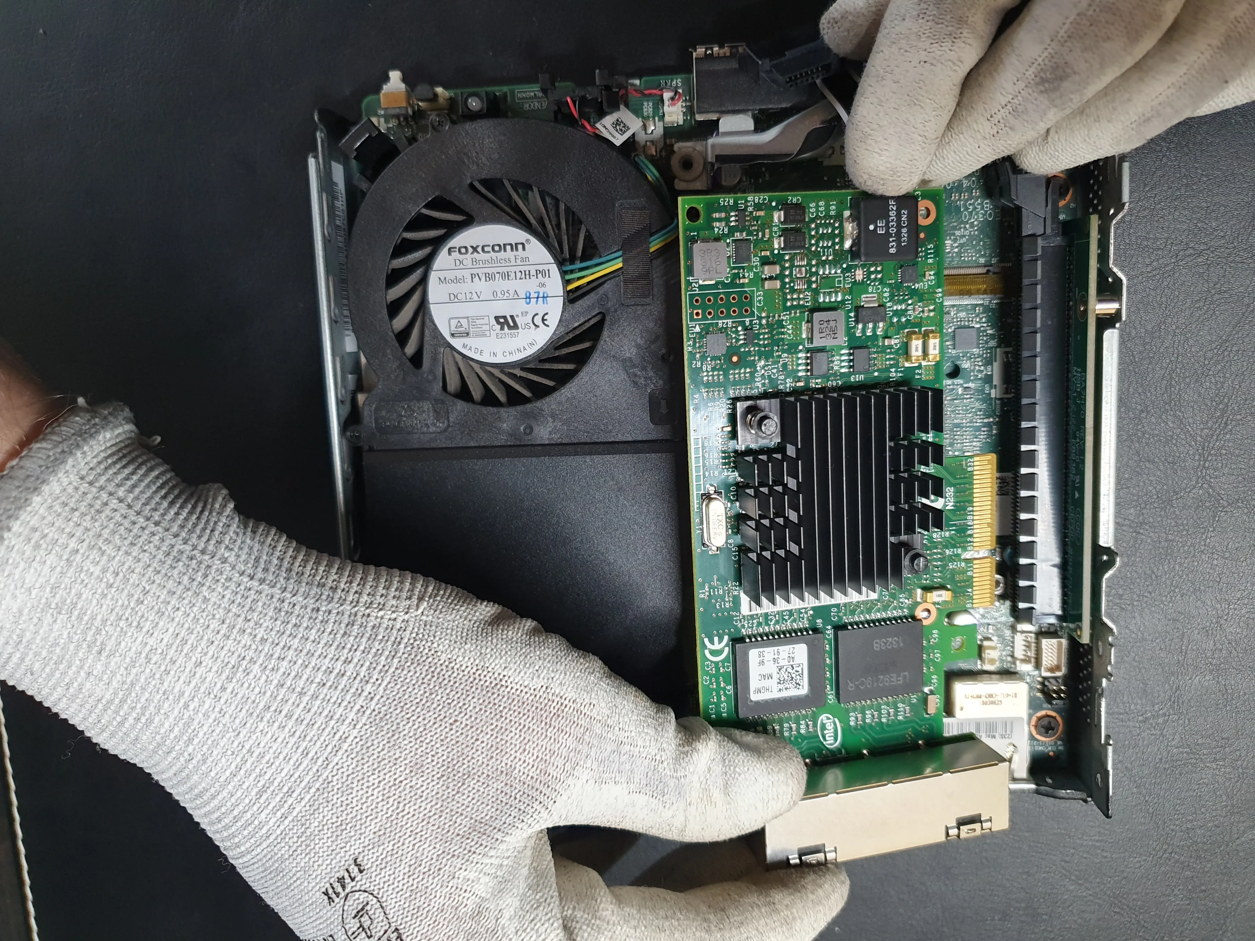
Everything put together without back cover:
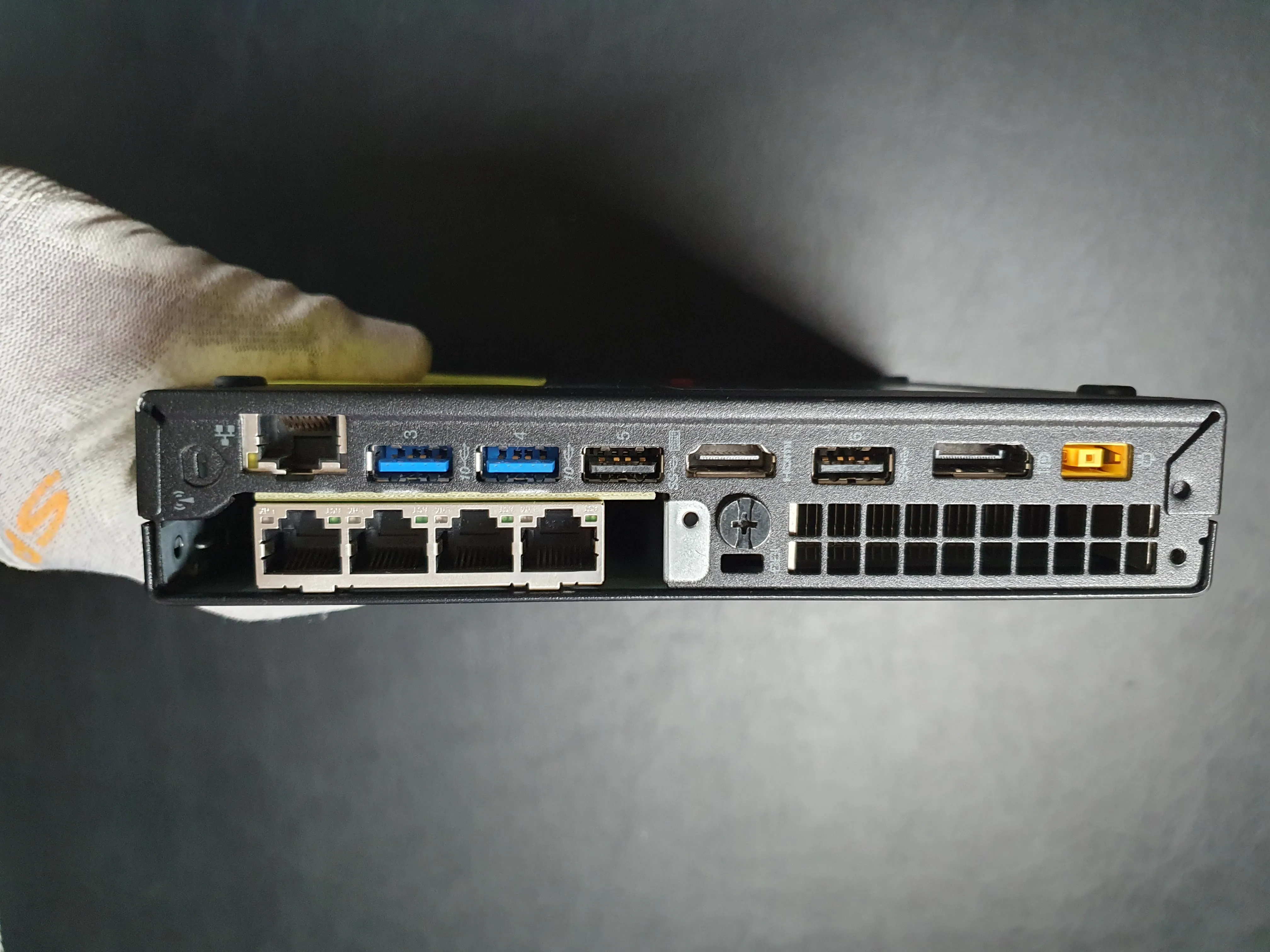
Complete Build with 3D printed Back cover.
If required you should update, reset and configure BIOS. You can refer to this GitHub link for more details on the steps related to this.
Software & USB Setup
These steps are for Linux systems. macOS and Windows have different procedures. If you’re unfamiliar with burning ISO images to USB drives, research the process for your operating system before proceeding.
If you prefer GUI tools over command-line, consider using:
- balenaEtcher (Windows/macOS/Linux) - User-friendly, cross-platform
- Rufus (Windows) - Fast and reliable
- Ventoy (Windows/macOS/Linux) - Supports multiple ISOs on one USB
All produce identical results - use whichever you’re comfortable with.
Downloading OPNsense
Download the latest OPNsense ISO from: https://opnsense.org/download/
Preparing the USB Drive
Identify Your USB Device
lsblkLocate your USB drive (typically /dev/sdd or similar). Note the device path.
Wipe the USB Drive
This will permanently erase all data on the USB drive. Backup any important files first.
sudo dd if=/dev/zero of=/dev/sdd bs=4M status=progressReplace /dev/sdd with your actual USB device path.
Verify the Downloaded Image
openssl sha256 OPNsense-25.7-vga-amd64.img.bz2Compare the output with the SHA256 checksum on the OPNsense download page.
SHA256 for version 25.7:
705e112e3c0566e6e568605173a8353a51d48074d48facf5c5831d2a0f7fb175For additional verification methods, refer to the OPNsense documentation.
Burn the Image to USB
sudo dd if=OPNsense-25.7-vga-amd64.img of=/dev/sdd bs=16k status=progressInstalling OPNsense
Pre-Installation Checklist
Before booting from USB, ensure:
- BIOS settings have been configured (see the GitHub link in the Hardware section)
- Boot order prioritizes USB devices
- Secure Boot is disabled (if applicable)
Installation Process
- Boot from USBInsert the USB drive and boot your system. Select the USB drive from the boot menu.
- Follow Installer PromptsThe OPNsense installer will guide you through the setup process. Select your preferred installation options (typically default settings work well).
- Verify Network InterfacesConfirm that all network interfaces are detected. For the Intel i350-T4 NIC, you should see
igb0,igb1,igb2, andigb3listed. - Set Root PasswordCreate a strong root password and store it securely. You will need this to access OPNsense.
NIC Compatibility: Non-Intel NICs or certain riser cards may have compatibility issues with OPNsense. The Intel i350-T4 has excellent driver support and is recommended for this build.
Network Interface Assignment
During installation, assign your WAN and LAN interfaces:
| Interface | Physical Port | Purpose |
|---|---|---|
| igb0 | Port 1 | WAN (Internet connection) |
| igb1 | Port 2 | LAN (Local network) |
| igb2 | Port 3 | Unassigned (for future use) |
| igb3 | Port 4 | Unassigned |
Integrated Interface: The M920q includes a built-in network interface (typically em0, though naming may vary). This is normal and can be left unassigned or used for management if desired.
Physical Port Labels: Label your ports with WAN/LAN designations using tape or a label maker. This prevents accidentally plugging cables into the wrong ports, which could expose your network or cause connectivity issues.
We do not configure VLANs during installation. These will be set up later through the web interface.
However, with the right knowledge you can set up VLANs here as well, it is completely up to you.
Post-Installation
Once the installation is complete, remove the USB and reboot the system. When it loads back up, the console will display the IP address for OPNsense web interface which you can reach through any browser.
Setting up OPNsense using UI
Initial Login
Access the web UI using the credentials: root / [your_password]
Setup Wizard
You’ll be presented with a setup wizard. You can either proceed through it or skip and configure manually.
Recommended Configuration:
Feel free to use your preferred DNS providers instead.
| Setting | Value | Notes |
|---|---|---|
| Domain | home.byteron.com | Use your own domain |
| Primary DNS Server | 1.1.1.1 | Temporary - will be replaced later |
| Secondary DNS Server | 9.9.9.9 | Temporary - will be replaced later |
| Override DNS | ✗ Uncheck | Critical - prevents ISP DNS usage |
We do not want to use our ISP DNS, so unchecking Override DNS is crucial. This ensures your DNS queries won’t leak to your ISP.
Optional: DNSSEC Configuration
If you want to enable DNSSEC support you should enable the following settings.
| Setting | Value |
|---|---|
| Enable DNSSEC Support | ✓ Check |
| Harden DNSSEC data | ✓ Check |
User Access, SSH and Keys
Depending on how you are setting this up, I’d recommend enabling SSH, at the very least temporarily so that you can troubleshoot any issues as they arise.
Once you’re done with the setup, I recommend only having certificate or key-based authentication for SSH. Password-based SSH is acceptable during setup only. Make a mental note on this going forward.
Disable IPv6
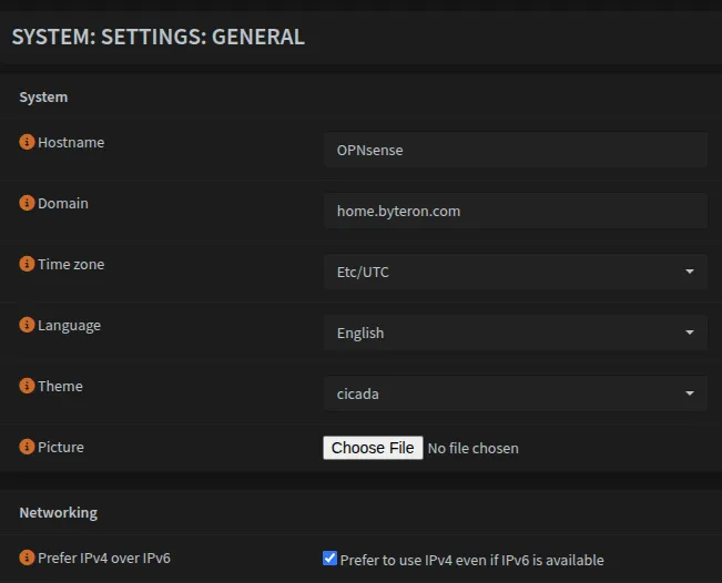
If you do not require IPv6 then you need to disable it in two locations found here:
| Location | Setting | Value |
|---|---|---|
System → Settings → General | Prefer IPv4 over IPv6 | ✓ Check |
Interfaces → Settings | Allow IPv6 | ✗ Uncheck |
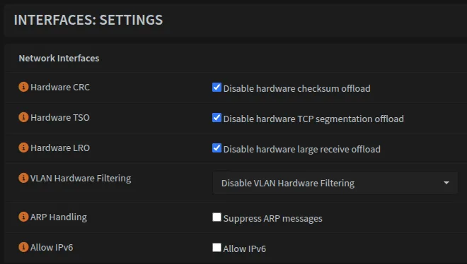
Optional: Hardware Offloading
If you’re not using Intel NICs, you may want to disable hardware offloading options that can be found here: Interfaces → Settings
Setting up VLANs
Navigate to Interfaces → Devices → VLAN and create the following VLANs:
| VLAN ID | Name | Purpose | Parent Interface |
|---|---|---|---|
VLAN10 | DMZ | Public-facing server | igb2 |
VLAN40 | SecWiFi | Secure WiFi | igb1 |
VLAN42 | IoT | IoT devices | igb1 |
VLAN44 | Guest | Guest network | igb1 |
VLAN46 | GoatNET | Bypass DNS/GeoBlocking | igb1 |
VLAN90 | Reserved | Optional for future use | igb1 |
Notice that VLAN10 (DMZ) uses igb2 as its parent interface while all other VLANs use igb1. This is intentional - we’re dedicating a separate physical interface for DMZ traffic performance isolation.
To do this, our OPNsense needs to have at least 3 ports, one for LAN, one for WAN and one for DMZ.
Once done, it should look like this:

Physical Port Configuration
OPNsense connects to two ports on the 24-port switch:
| Switch Port | OPNsense Interface | Type | Traffic |
|---|---|---|---|
| Port 23 | igb1 | Trunk | LAN, VLAN40, VLAN42, VLAN44, VLAN46 |
| Port 24 | igb2 | Dedicated | DMZ VLAN10 only |
Note that igb1 and igb2 refer to the two physical interfaces on OPNsense.
Details on how to set up network switches and VLANs can be found here.
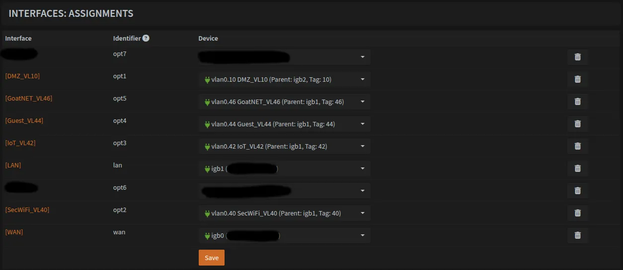
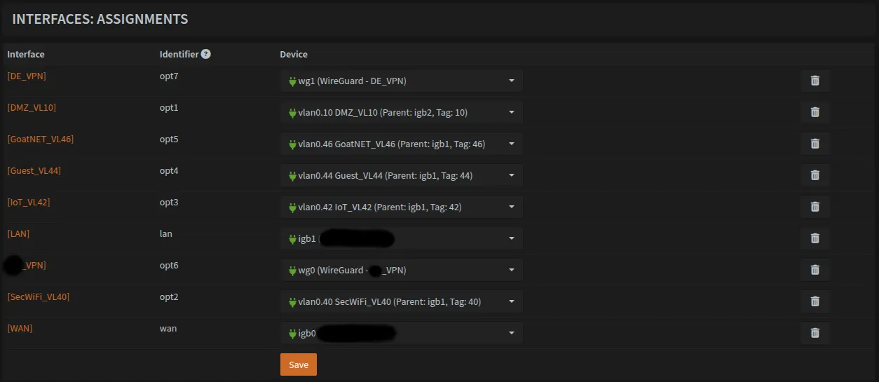
Assigning VLANs to Interfaces
Navigate to Interfaces → Assignments and assign each VLAN to a virtual interface. Once complete, your assignments should include all the VLANs listed above.
Note that I redacted a few fields as I forgot to take a screenshot earlier in the setup.
Configuring IP Addresses
Now the tedious part, for each VLAN interface, you need to:
- Enable the interface
- Assign a static IP address
IP Addressing Scheme
To keep things organized, the third octet matches the VLAN ID:
Base: 10.0.0.1/24 (LAN)Pattern: 10.0.[VLAN_ID].1/24Examples:
VLAN10→10.0.10.1/24VLAN40→10.0.40.1/24VLAN46→10.0.46.1/24
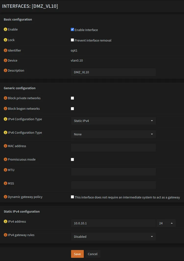
Navigate to each interface (e.g., Interfaces → [DMZ_VL10]) and configure it with the appropriate static IP following this pattern.
Repeat this process for all VLAN interfaces as shown in the screenshot for DMZ_VL10
DNSmasq & DHCP
We’ll use DNSmasq for local DNS resolution and DHCP services across all VLANs.
Configuring DNSmasq
Navigate to Services → DNSmasq DNS & DHCP → General:
- Select the interfaces that need the service
- Enable the service
- Change the listening port from
53to5335(since AdGuard will use port53)
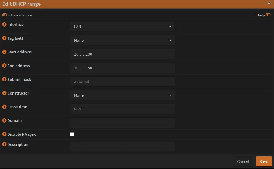
Setting Up DHCP Ranges
Navigate to Services → DNSmasq DNS & DHCP → DHCP Ranges and create IP ranges for each VLAN.
DHCP Range Strategy
Each network uses the same range pattern (.100 to .150), providing 51 IP addresses per network. This makes management consistent across all VLANs. Adjust ranges if you need more devices per VLAN.
| Network | Gateway | DHCP Start | DHCP End | Available IPs |
|---|---|---|---|---|
| LAN | 10.0.0.1 | 10.0.0.100 | 10.0.0.150 | 51 |
| VLAN10 (DMZ) | 10.0.10.1 | 10.0.10.100 | 10.0.10.150 | 51 |
| VLAN40 (SecWiFi) | 10.0.40.1 | 10.0.40.100 | 10.0.40.150 | 51 |
| VLAN42 (IoT) | 10.0.42.1 | 10.0.42.100 | 10.0.42.150 | 51 |
| VLAN44 (Guest) | 10.0.44.1 | 10.0.44.100 | 10.0.44.150 | 51 |
| VLAN46 (GoatNET) | 10.0.46.1 | 10.0.46.100 | 10.0.46.150 | 51 |
Example screenshot of editing DHCP range for LAN. Repeat this process for each network in the table above.
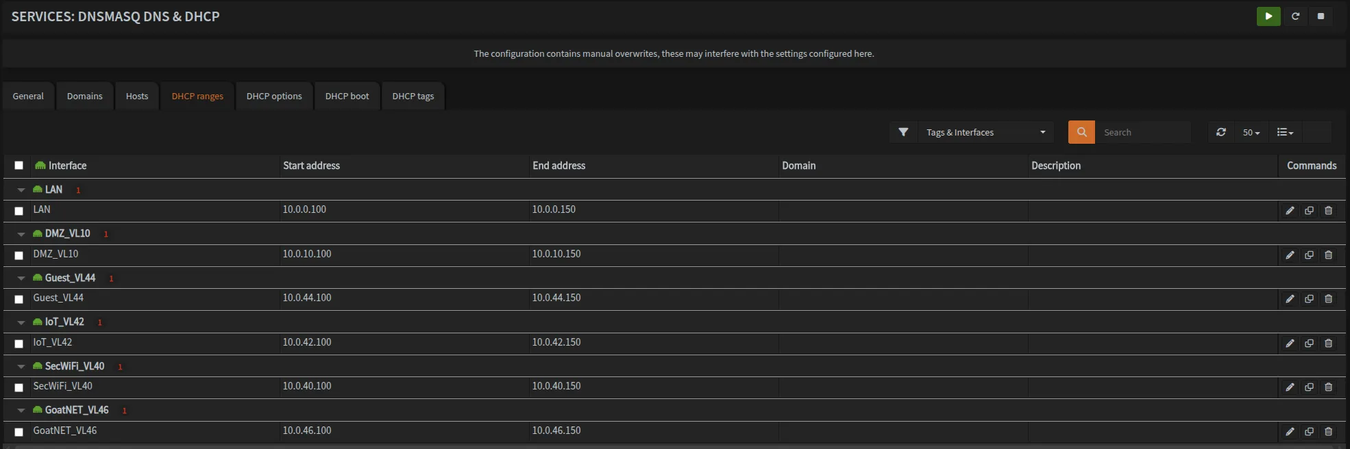
Once configured, your DHCP ranges should look like this:
VPN Setup: Mullvad + WireGuard
I’ve used Mullvad as my VPN of choice for many years. If you want a privacy-focused, performant VPN, Mullvad is the choice. I’m not sponsored by them, but I’d recommend them 10/10 times.
Generating Configuration Files
Use Mullvad’s WireGuard Config Generator to create configuration files for your tunnels.
- Generate a new key or use an existing one
- Select your preferred country, city, and server
- Download and open the config file
Example Configuration File:
[Interface]
# Device: Funky Name
PrivateKey = REDACTED_PRIVATE_KEY
Address = 10.65.196.16/32
DNS = 10.64.0.1

[Peer]
PublicKey = REDACTED_PUBLIC_KEY
AllowedIPs = 0.0.0.0/0
Endpoint = 185.209.196.77:51819
Note down all fields - you’ll need them in the following steps.
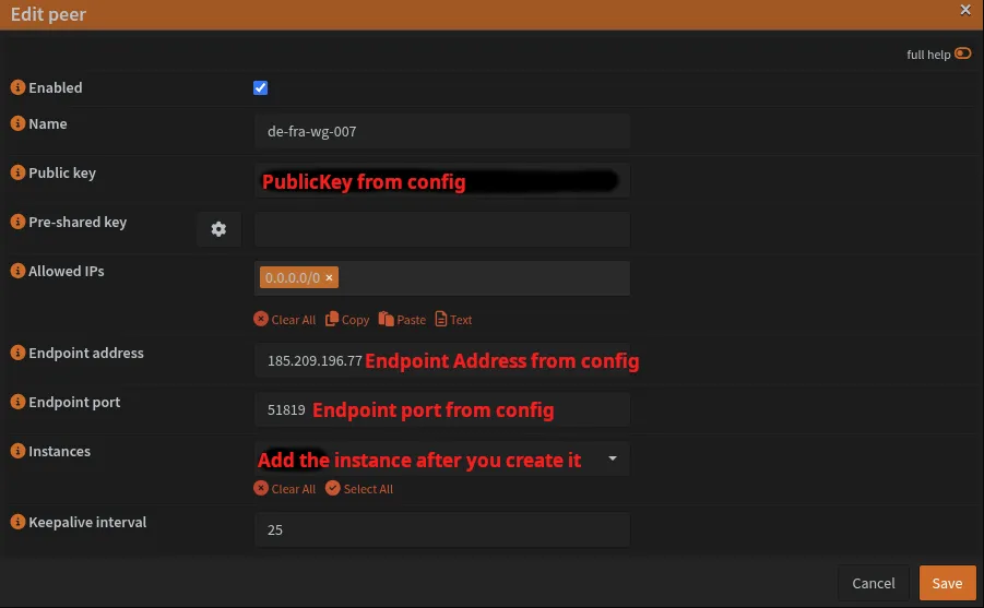
Creating WireGuard Peers
Navigate to VPN → WireGuard → Peers and create a peer for each server:
| Field | Value |
|---|---|
| Name | de-fra-wg-007 |
| Public Key | [PublicKey from config] |
| AllowedIPs | 0.0.0.0/0 |
| Endpoint Address | [Endpoint from config] |
| Endpoint Port | [Endpoint port from config] |
| Keepalive | 25 |
Leave the Instance field blank for now.
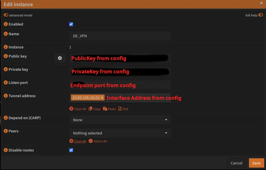
Creating WireGuard Instances
Navigate to VPN → WireGuard → Instances and create an instance:
| Field | Value |
|---|---|
| Name | DE_VPN |
| Public Key | [PublicKey from config] |
| Private Key | [PrivateKey from config] |
| Listen Port | 51819 |
| Tunnel Address | 10.65.196.16/32 [Interface Address from config] |
| Peers | de-fra-wg-007 |
Repeat for Second VPN
Create a second peer and instance for redundancy. Make sure that you use a different listen port for each VPN instance.
| VPN Instance | Listen Port | Purpose |
|---|---|---|
| VPN_1 (UK_VPN) | 51820 | Primary VPN tunnel |
| VPN_2 (DE_VPN) | 51819 | Secondary VPN tunnel (redundancy) |
| VPN_3 (example) | 51818 | Example Third VPN tunnel |
Make sure that each instance has at least 1 peer assigned to it.
For each instance you may want to assign multiple peers.
For example, DE_VPN instance may have 2+ peers, each being a different server like de-fra-wg-007 and de-fra-wg-001
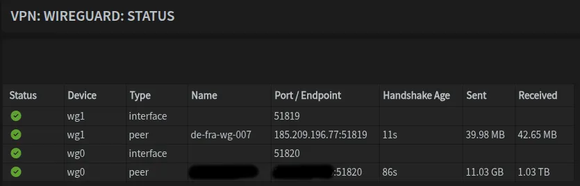
Enabling and Verifying Tunnels
- Enable WireGuard in the Instance tab
- Navigate to
VPN → WireGuard → Status - Verify connection status shows recent handshakes and data transfer
It should look something like this:
Assigning WireGuard Interfaces
Navigate to Interfaces → Assignments and add both WireGuard interfaces wg0 and wg1. Your interface list should now include all VLANs, LAN, WAN, and the two WireGuard interfaces.
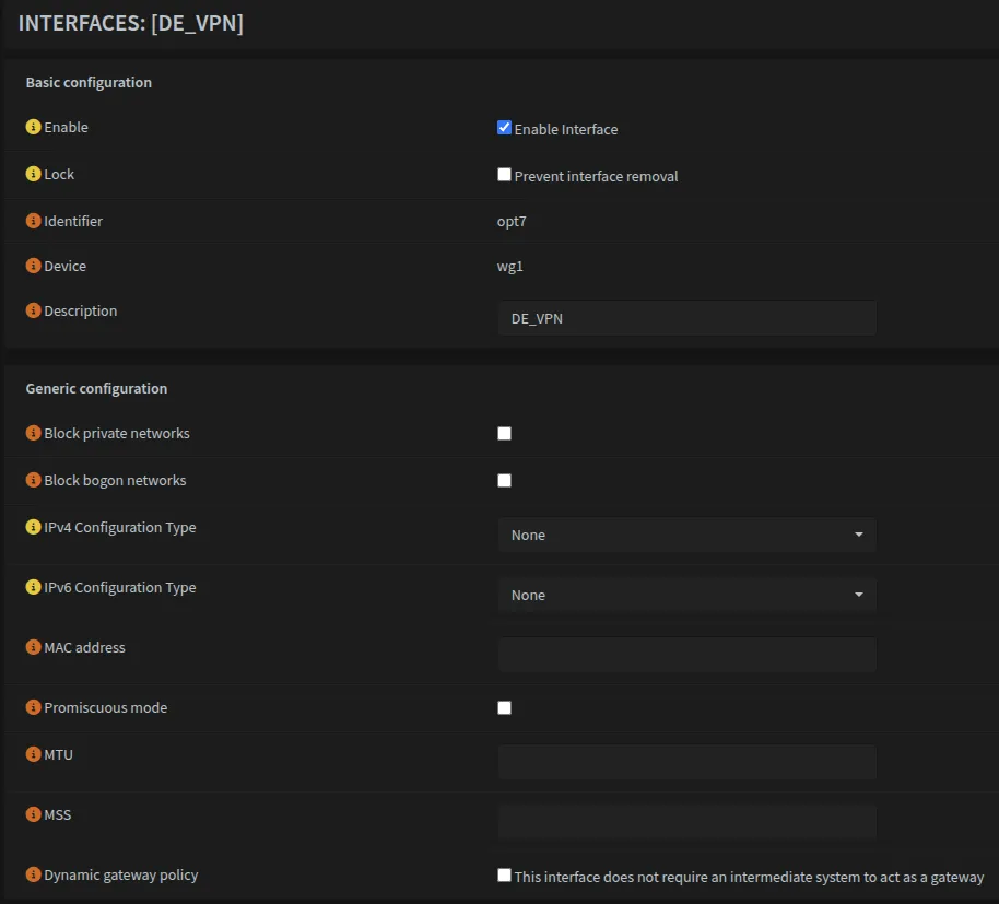
Configuring WireGuard Interface Settings
For each WireGuard interface, you need to enable it but NOT assign a gateway at the interface level.
Navigate to Interfaces → [UK_VPN] (or whatever you named your first VPN interface):
| Field | Value |
|---|---|
| Enable | ✓ Check |
| Lock | Unchecked |
| Description | UK_VPN (or your chosen name) |
| IPv4 Configuration Type | None |
| IPv6 Configuration Type | None |
VPN Gateways
Creating Gateway Entries
Navigate to System → Gateways → Configuration and create a gateway for each VPN tunnel:
| Field | VPN 1 (Primary) | VPN 2 (Secondary) |
|---|---|---|
| Name | WAN_UK_VPN | WAN_DE_VPN |
| Interface | [Your VPN interface] | DE_VPN |
| Address Family | IPv4 | IPv4 |
| Priority | 1 | 2 |
| IP Address | [Config Address - 1]* | 10.65.196.15 |
| Far Gateway | ✓ | ✓ |
| Monitor IP | 100.64.0.2 | 100.64.0.1 |
Take the tunnel address from the config file and subtract 1 from the last octet:
If tunnel address is: 10.65.196.16/32
Gateway IP would be: 10.65.196.15
This only works if your tunnel address ends with a number greater than 1. Mullvad’s WireGuard implementation doesn’t actually use a traditional gateway model so you could technically use ANY IP in the Mullvad network range.
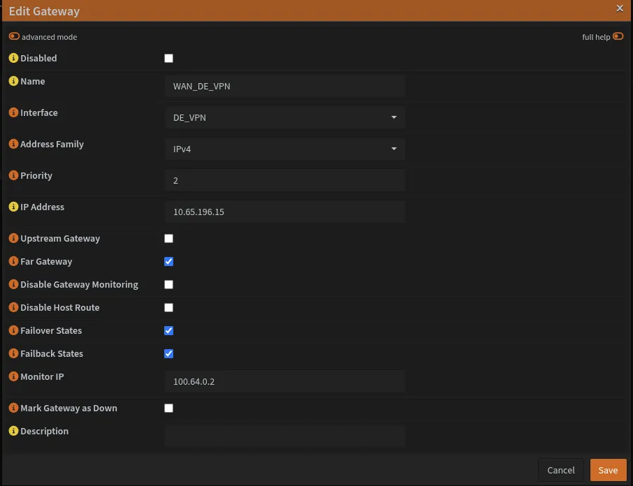
The Monitor IP addresses 100.64.0.1 and 100.64.0.2 are Mullvad DNS servers used to check gateway health.
You can find the list of Mullvad DNS servers and what they block on GitHub
Modify WAN Gateway
Edit the WAN_DHCP gateway and change its priority to 254 (lowest priority).
Creating Gateway Group
Navigate to System → Gateways → Group and create a failover group:
| Field | Value |
|---|---|
| Group Name | WAN_VPN_GRP |
| Gateway Priority | WAN_UK_VPN: Tier 1 WAN_DE_VPN: Tier 2 WAN_DHCP: Never |
| Trigger Level | Member Down or Packet Loss/High Latency |

Enable Default Gateway Switching
Navigate to System → Gateways → Configuration and enable Default Gateway Switching.
This setting is required for VPN failover to work correctly. When enabled, OPNsense automatically switches the default gateway based on gateway status and priority.
With default gateway switching enabled, if both VPN tunnels go down, the default gateway will fall back to WAN. This is why the kill switch rule on VPN_OUT_IG is essential - it blocks internet traffic when VPN is unavailable, preventing leaks to your ISP.
Static Routes
Static routes are essential for VPN functionality. Without them, you create a circular routing problem: traffic can’t establish the VPN tunnel because all traffic is being routed through the tunnel that doesn’t exist yet.
Understanding the Requirement
You must create a static route for every VPN endpoint IP address from your WireGuard configuration files. Even if you only plan to use one tunnel initially, add routes for all endpoints you’ve configured as peers. This ensures seamless failover if you later enable backup tunnels.
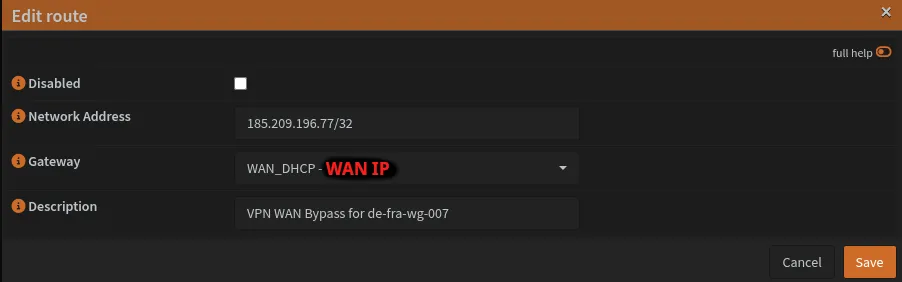
Creating Static Routes
Navigate to System → Routes → Configuration and add a static route for each VPN endpoint.
Example Routes:
For each WireGuard peer you created earlier, add its endpoint:
Route 1 - UK Server:
| Field | Value |
|---|---|
| Network Address | 185.65.135.202/32 |
| Gateway | WAN_DHCP |
| Description | VPN WAN Bypass for uk-lon-wg-101 |
Route 2 - DE Server:
| Field | Value |
|---|---|
| Network Address | 185.209.196.77/32 |
| Gateway | WAN_DHCP |
| Description | VPN WAN Bypass for de-fra-wg-007 |
If you add additional WireGuard peers in the future, you must create static routes for their endpoint IPs as well. Forgetting this will cause connection failures due to circular routing.
Finding Your Endpoint Addresses
The endpoint addresses come from the [Peer] section of your Mullvad WireGuard configuration files:
[Peer]
PublicKey = REDACTED_PUBLIC_KEY
AllowedIPs = 0.0.0.0/0
Endpoint = 185.209.196.77:51819  ← This IP address
Extract the IP address (without the port) and use it in the Network Address field with /32 suffix. Once done, it should look like this:
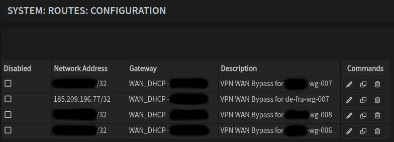
Note that you see 4 entries for 4 different servers/regions.
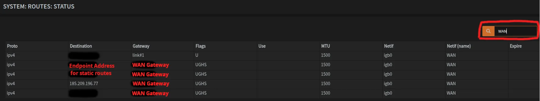
Verification
After adding all static routes, verify they appear in your routing table. You can go to System → Routes → Status and you can filter by WAN. You should see entries for each VPN endpoint IP routing through your WAN gateway.
DNS Resolver (Unbound)
General Configuration
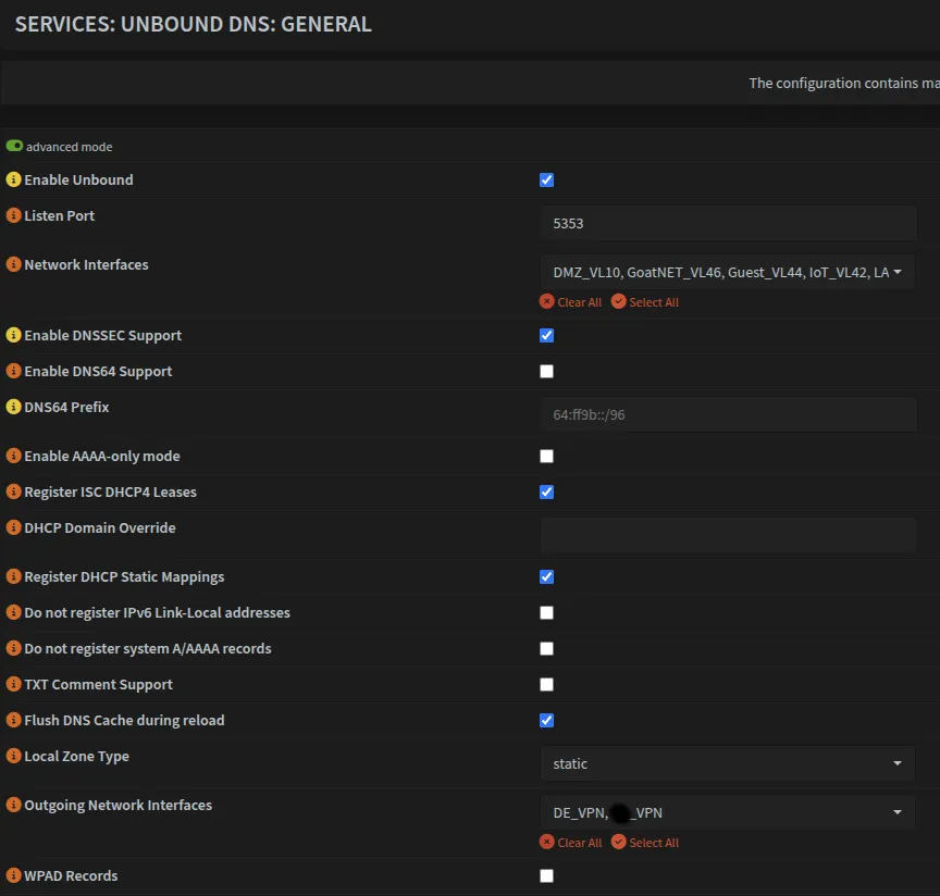
Navigate to Services → Unbound DNS → General and configure the basic settings. Make sure to change the listen port to 5353 so it does not conflict with AdGuard.
| Setting | Value |
|---|---|
| Network Interfaces | LAN, VLAN10, VLAN40, VLAN42, VLAN44, VLAN46 |
| Listen Port | 5353 |
| DNSSEC | ✓ |
| DHCP Registration | ✓ |
| DHCP Static Mappings | ✓ |
| Local Zone Type | static |
Advanced Mode Settings
Enable Advanced Mode (top left) to access additional options:
| Setting | Value |
|---|---|
| Outgoing Network Interfaces | DE_VPN, UK_VPN |
Do not include WAN in the Outgoing Network Interfaces. This ensures all DNS queries go through the VPN tunnels, preventing DNS leaks to your ISP.
If DNS resolution fails during setup, the issue is elsewhere:
- Verify VPN tunnels are active (
VPN → WireGuard → Status) - Check static routes are configured
- Confirm gateway group is working
- Verify AdGuard is running on port
53
Adding WAN as an outgoing interface creates the exact DNS leak this setup prevents.
Temporary troubleshooting only: If you must add WAN to diagnose issues, remove it immediately after identifying the problem. This creates a DNS leak and exposes your queries to your ISP.
Once done, it should look something like this:
Advanced Tab Configuration
Navigate to the Advanced tab and enable the following security options:
| Setting | Value |
|---|---|
| Hide Identity | ✓ Enable |
| Hide Version | ✓ Enable |
| Prefetch Support | ✓ Enable |
| Prefetch DNS Key Support | ✓ Enable |
| Harden DNSSEC data | ✗ Disable |
“Harden DNSSEC data” adds validation overhead. If you experience slow DNS (>200ms), try disabling this setting first.
Creating Custom Configuration Files on OPNsense
SSH into OPNsense and create the necessary configuration files for local domain handling.
Optional: Install nano
For beginners, I recommend using the nano text editor which does not come with OPNsense so you have to install it yourself. Alternatively, you can install Vim, Emacs or vi and use that instead.
pkg install nanoYou can use your preferred editor in the steps below, just replace nano command.
Create the targets file:
nano /usr/local/opnsense/service/templates/OPNsense/Unbound/+TARGETSContent:
private_domains.conf:/usr/local/etc/unbound.opnsense.d/private_domains.confCreate the private domains configuration:
nano /usr/local/etc/unbound.opnsense.d/private_domains.confContent:
server:
  local-data: "home.byteron.com. 3600 IN SOA opnsense.home.byteron.com. admin.byteron.com. 2021110201 86400 7200 3600000 3600"
  local-zone: "home.byteron.com" static
Apply and verify the configuration:
# Generate template
configctl template reload OPNsense/Unbound

# Show generated file
cat /usr/local/etc/unbound.opnsense.d/private_domains.conf

# Check if configuration is valid
configctl unbound check
Query Forwarding
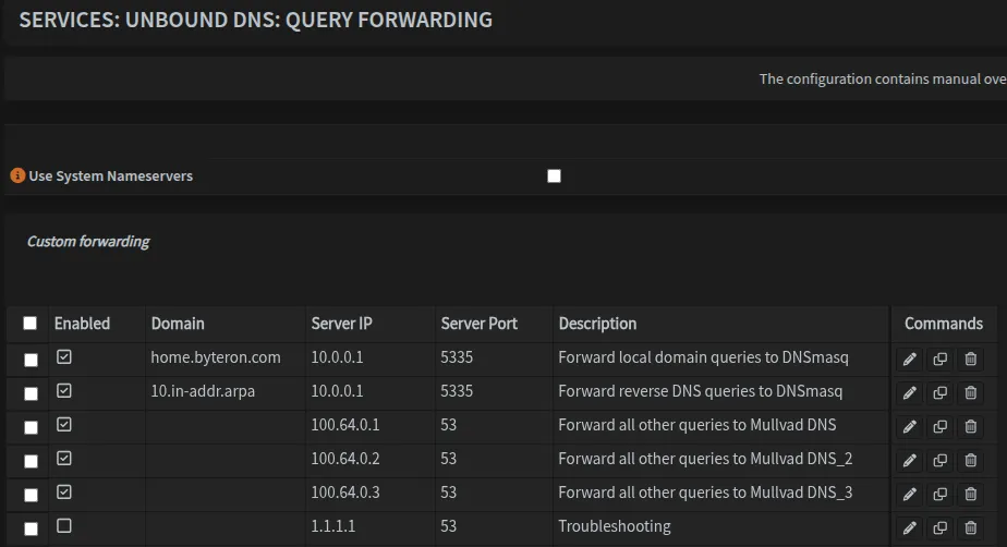
Navigate to Services → Unbound DNS → Query Forwarding and configure forwarding rules:
| Domain | Server IP | Server Port | Purpose |
|---|---|---|---|
| home.byteron.com | 10.0.0.1 | 5335 | Forward local domain queries to DNSmasq |
| 10.in-addr.arpa | 10.0.0.1 | 5335 | Forward reverse DNS queries to DNSmasq |
| [Leave blank]** | 100.64.0.1 | 53 | Forward all other queries to Mullvad DNS |
| [Leave blank]** | 100.64.0.2 | 53 | Forward all other queries to Mullvad DNS_2 |
| [Leave blank]** | 100.64.0.3 | 53 | Forward all other queries to Mullvad DNS_3 |
** Leave the Domain field blank for default upstream servers that handle all non-local queries.
Note that I included 3 Mullvad DNS servers so that in rare cases where one of them goes down, we are still able to resolve public domains.
10.in-addr.arpa is a special Internet domain used for reverse DNS lookups of IP addresses within the private 10.0.0.0/8 address space.
You can learn more on Reverse DNS lookup wiki.
Once completed, it should look like this. Also note that we have disabled entry for 1.1.1.1 which was used for testing purposes.
Firewall Configuration
Now we need to configure firewall rules to allow traffic, since the default action is always BLOCK.
The interface group approach is inspired by Michael Schnerring’s OPNsense guide. This method simplifies rule management significantly.
Creating Interface Groups
Navigate to Firewall → Groups and create the following groups:
| Group Name | Member Interfaces | Purpose |
|---|---|---|
| VPN_OUT_IG | LAN, VLAN10, VLAN40, VLAN42, VLAN44, VLAN46 | Interfaces for VPN-bound traffic |
| SEC_LAN_IG | LAN, VLAN40 | Secure/trusted networks (LAN + SecWiFi) |
| DNS_ADGUARD_IG | LAN, VLAN10, VLAN40, VLAN42, VLAN44 | Networks using AdGuard DNS + Blocking |
| NO_ADGUARD_IG | VLAN46 | Networks bypassing AdGuard (No Blocking) |
| WAN_OUT_IG** | **See Note below | WAN-bound traffic (selective routing) |
It should look something like this:
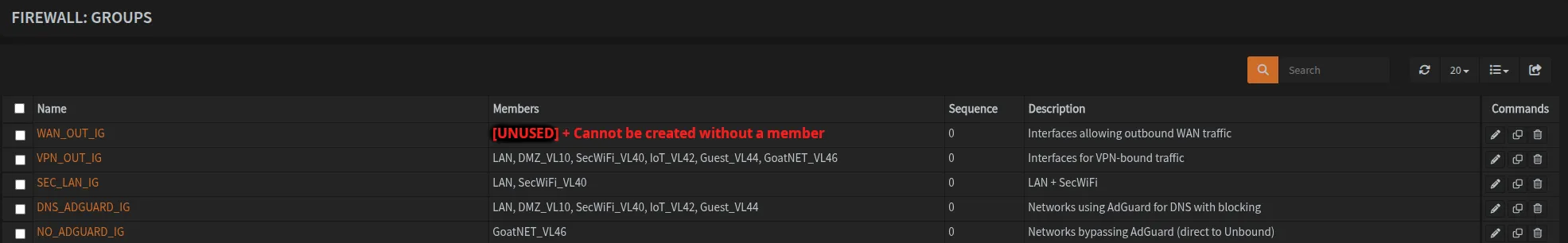
We leave WAN_OUT_IG empty in this configuration since nothing routes directly through WAN (everything goes through VPN).
You cannot create an interface group without any members, so if you don’t plan to use WAN bypass routing, skip creating this group entirely. You should also skip WAN_OUT_IG rules that are created later.
You would create this group and rules if you have a specific interface group that requires direct WAN access, for example a specific VLAN. In my setup, this behaviour is not wanted or needed.
Firewall Aliases
Aliases simplify firewall rule management and make maintenance easier. Navigate to Firewall → Aliases to create the following.
Network & Host Aliases
My setup has aliases for every device on the network which includes servers, cameras, printers, network gear and everything else. There are also nested aliases to help group devices further. I recommend you do the same according to your needs. Since my alias list contains sensitive information I am unable to share a screenshot for it.
| Name | Type | Content | Description |
|---|---|---|---|
| IPv4_RFC1918 | Networks | 10.0.0.0/8 172.16.0.0/12 192.168.0.0/16 | Private IPv4 RFC1918 addresses |
| SELECTIVE_ROUTING | Hosts | [See note] | External Hosts reachable directly through WAN bypassing VPN |
| MULLVAD_ENDPOINTS | Hosts | [Endpoint addresses from config] | VPN endpoint addresses for tunnel establishment |
This is an alias for EXTERNAL host that you wish to reach through WAN and bypass VPN.
For example, netflix.com
Port Aliases
| Name | Type | Content | Description |
|---|---|---|---|
| PORTS_ANTI_LOCKOUT | Port(s) | 443, 22 | OPNsense admin interface ports |
| ALL_PORTS | Port(s) | 1:65535 | All ports (use for troubleshooting) |
| PORTS_OUT_LAN | Port(s) | See table below | Intranet allowed ports |
| PORTS_OUT_WAN | Port(s) | See table below | Internet allowed ports |
| SERVICE_PORTS | Port(s) | [Not shown - customize per your services] | Ports for DMZ services |
Optional: Aliases:
| Name | Type | Content | Description |
|---|---|---|---|
| PLEX_PORTS | Port(s) | 443, 1900, 3005, 8324, 32400, 32469, 32410:32414 | Plex server required ports |
| FILE_SHARING | Port(s) | 137:139, 445 | NetBIOS & SMB ports |
| LOCAL_PROXY | Host(s) | 10.0.0.Y | Reverse Local Proxy IP |
| EXTERNAL_PROXY | Host(s) | 10.0.0.Z | Reverse Proxy IP |
| PLEX | Host(s) | 10.0.10.X | IP address for PLEX |
| STEAM_PORTS | Port(s) | 4380, 27000:27100 | Steam client and game servers |
The optional aliases are examples you may want depending on your specific setup and services. Adjust IP addresses to match your actual server locations. Create only the aliases you need for your specific setup.
PORTS_OUT_LAN - Intranet allowed ports:
| Port(s) | Service |
|---|---|
| 5353:5354 | mDNS |
| 123 | NTP |
| 137 | NetBIOS |
| 21 | FTP |
| 22 | SSH |
| 161 | SNMP |
| 80 | HTTP |
| 8080 | HTTP alt / UniFi communication |
| 443 | HTTPS |
| 8443 | HTTPS alt / UniFi GUI/API |
| 8880 | UniFi HTTP portal redirection |
| 10001 | UniFi device discovery |
| 5001 | iPerf |
| 5900 | VNC |
| 3389 | RDP |
3080 | AdGuard UI |
| 49152:65535 | Ephemeral ports |
PORTS_OUT_WAN - Internet allowed ports:
| Port(s) | Service |
|---|---|
| 22 | SSH/SFTP |
| 80 | HTTP |
| 8080 | HTTP alt |
| 443 | HTTPS |
| 8443 | HTTPS alt |
| 465 | SMTPS |
| 587 | SMTPS |
| 993 | IMAPS |
| 49152:65535 | Ephemeral ports |
My PORTS_OUT_WAN alias also contains other aliases such as STEAM_PORTS, TOOL_PORTS, APPLICATION_PORTS etc. The process of figuring out what application requires what port can be tedious but can be easily done by utilizing Firewall → Log Files → Live View and adding appropriate filters for interfaces, source devices and action being blocked. With the filter set, you simply launch the application and by looking at the logs you can easily figure out what ports are needed. Hint: They are the ones getting blocked.
Egress filtering can be challenging to manage. If you encounter issues with applications not
working, consider using the ALL_PORTS alias for PORTS_OUT_WAN or PORTS_OUT_LAN to simplify
troubleshooting. You can always tighten the rules once everything is working.
What are MULLVAD_ENDPOINTS for?
The MULLVAD_ENDPOINTS alias contains your VPN endpoint addresses and will be used to create rules that allow tunnel establishment even when all traffic is routed through the VPN. This solves the circular routing problem mentioned earlier.
NAT - Network Address Translation
Outbound NAT Rules
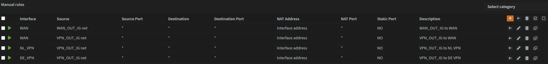
Navigate to Firewall → NAT → Outbound and select Manual Outbound NAT rule generation.
Create the following outbound NAT rules:
| Interface | Source Address | Description | Enabled |
|---|---|---|---|
| WAN | WAN_OUT_IG net | WAN_OUT_IG to WAN | Disabled |
| WAN | VPN_OUT_IG net | VPN_OUT_IG to WAN | Yes |
| UK_VPN | VPN_OUT_IG net | VPN_OUT_IG to UK VPN | Yes |
| DE_VPN | VPN_OUT_IG net | VPN_OUT_IG to DE VPN | Yes |
It should look like this once done:
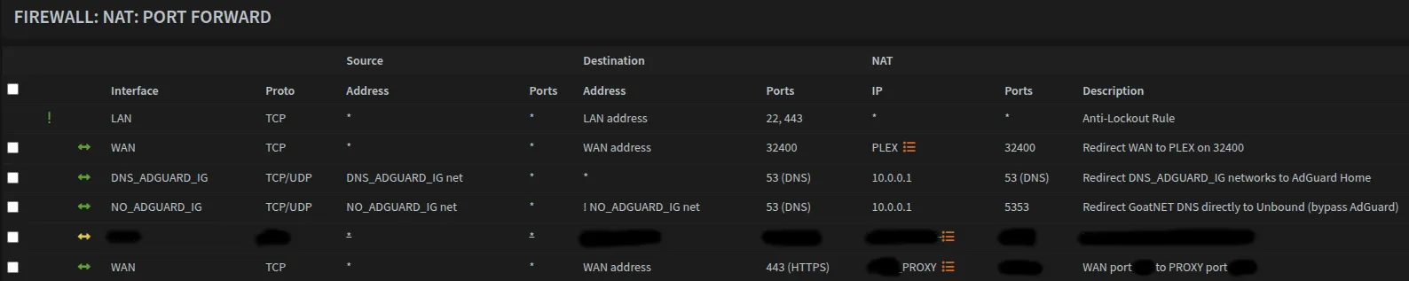
NAT DNS Redirect
Navigate to Firewall → NAT → Port Forward (or Firewall → NAT → Destination NAT in newer OPNsense versions) to redirect DNS queries to the appropriate DNS resolver.
Redirect networks using AdGuard:
| Field | Value |
|---|---|
| Interface | DNS_ADGUARD_IG |
| Protocol | TCP/UDP |
| Source | DNS_ADGUARD_IG net |
| Destination | any |
| Destination Port Range | 53 (DNS) |
| Redirect Target IP | 10.0.0.1 |
| Redirect Target Port | 53 (DNS) |
| Description | Redirect DNS_ADGUARD_IG networks to AdGuard Home |
Redirect VLAN46 to bypass AdGuard:
| Field | Value |
|---|---|
| Interface | NO_ADGUARD_IG |
| Protocol | TCP/UDP |
| Source | NO_ADGUARD_IG net |
| Destination | any |
| Destination Port Range | 53 (DNS) |
| Redirect Target IP | 1.1.1.1 |
| Redirect Target Port | 53 (DNS) |
| Description | Redirect GoatNET DNS directly to 1.1.1.1 (bypass AdGuard) |
This traffic still routes through the VPN tunnels but uses Cloudflare DNS instead of Mullvad DNS.
Optional: Reverse Proxy Redirect
If running a reverse proxy, create this port forward rule. You may also want a near-identical rule for HTTP traffic.
| Field | Value |
|---|---|
| Interface | WAN |
| Protocol | TCP |
| Source | Any |
| Destination | WAN address |
| Destination Port Range | 443 (HTTPS) |
| Redirect Target IP | PROXY [Alias] |
| Redirect Target Port | XXXX |
| Description | WAN redirect port 443 to PROXY port XXXX |
Replace XXXX with the actual port your reverse proxy listens on. This is configured when you set
up your reverse proxy.
Optional: Plex Remote Access
For Plex remote access, create this port forward rule:
Navigate to Firewall → NAT → Port Forward (or Destination NAT in newer versions) and click Add to create a new rule:
| Field | Value |
|---|---|
| Interface | WAN |
| Protocol | TCP |
| Source | Any |
| Destination | WAN address |
| Destination Port Range | 32400 |
| Redirect Target IP | PLEX [Alias] |
| Redirect Target Port | 32400 |
| Description | Redirect WAN to PLEX on 32400 |
| NAT reflection | Disable |
| Filter rule association | Manual |
This port forward exposes your Plex server directly to the internet on WAN, bypassing VPN protection.
While necessary for Plex remote access, be aware of its security implications.
Once completed, it should look like this:
Firewall Rules
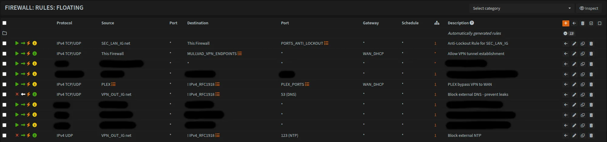
Floating Rules
Navigate to Firewall → Rules → Floating and create the following rules:
| Action | Interface | Direction | Quick | Protocol | Source | Destination | Dest. Port | Gateway | Description |
|---|---|---|---|---|---|---|---|---|---|
| Pass | SEC_LAN_IG | in | Yes | TCP/UDP | SEC_LAN_IG net | This Firewall | PORTS_ANTI_LOCKOUT | * | Anti-Lockout rule for SEC_LAN_IG |
| Pass | * | out | Yes | TCP/UDP | This Firewall | MULLVAD_ENDPOINTS | * | WAN_DHCP | Allow VPN tunnel establishment |
| Pass | * | in | Yes | TCP/UDP | PLEX | !IPv4_RFC1918 | PLEX_PORTS | WAN_DHCP | PLEX bypass VPN to WAN |
| Block | DNS_ADGUARD_IG | in | Yes | TCP/UDP | VPN_OUT_IG net | !IPv4_RFC1918 | 53 (DNS) | * | Block external DNS - prevent leaks |
| Block | VPN_OUT_IG | in | Yes | UDP | VPN_OUT_IG net | !IPv4_RFC1918 | 123 (NTP) | * | Block external NTP - prevent leaks |
Never use * as source for the Anti-Lockout rule. Restrict it to SEC_LAN_IG net or your trusted networks only.
Once done it should look like this. I’ve redacted some additional rules that are unique to my network.
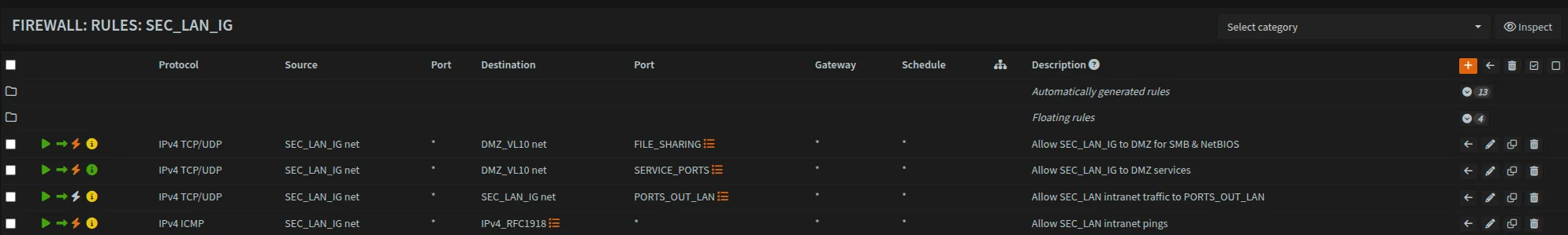
SEC_LAN_IG Rules
Navigate to Firewall → Rules → SEC_LAN_IG and create the following rules:
| Action | Protocol | Source | Destination | Dest. Port | Description |
|---|---|---|---|---|---|
| Pass | TCP/UDP | SEC_LAN_IG net | DMZ_VL10 net | FILE_SHARING | Allow SEC_LAN_IG to DMZ for SMB & NetBIOS |
| Pass | TCP/UDP | SEC_LAN_IG net | DMZ_VL10 net | SERVICE_PORTS | Allow SEC_LAN_IG to DMZ services |
| Pass | TCP/UDP | SEC_LAN_IG net | SEC_LAN_IG net | PORTS_OUT_LAN | Allow SEC_LAN intranet traffic |
| Pass | ICMP | SEC_LAN_IG net | IPv4_RFC1918 | - | Allow SEC_LAN intranet pings |
Rule Explanation:
FILE_SHARINGrule: AllowsLANandSecWiFito access file shares (SMB/NetBIOS) on DMZ serverSERVICE_PORTSrule: Allows access to other DMZ services (web interfaces, APIs, etc.) defined inSERVICE_PORTSalias (Common examples: 80, 443, 8080, 8443, or application-specific ports)- Intranet traffic rule: Allows
LANandSecWiFidevices to communicate with each other on specified ports - ICMP rule: Allows pinging to
IPv4_RFC1918only, internet pings are handled by the ICMP rule onVPN_OUT_IGwhich routes them through the VPN gateway
Access to DMZ is controlled through explicit SEC_LAN_IG rules (rules 1 and 2 above), not through interface group membership.
DMZ Network Isolation:
VLAN10 (DMZ)is included inVPN_OUT_IGandDNS_ADGUARD_IGfor internet and DNS access- DMZ is NOT included in
SEC_LAN_IG- this is intentional for security - Access to DMZ services is controlled through explicit
SEC_LAN_IGinterface rules only - This prevents DMZ from initiating connections back to trusted networks (
LAN/SecWiFi)
Why this matters:
If your DMZ server is compromised, the attacker cannot scan or access your personal devices on LAN/SecWiFi. They’re limited to what’s explicitly allowed through firewall rules.
Optional: WAN_OUT_IG Rules
As mentioned earlier, if you need specific interface traffic to bypass the VPN and use WAN directly then you need to make sure that the necessary interface is added to WAN_OUT_IG interface group which wasn’t created earlier.
Then create the rule below.
| Action | Protocol | Source | Destination | Dest. Port | Description |
|---|---|---|---|---|---|
| Pass | TCP/UDP | WAN_OUT_IG net | !IPv4_RFC1918 | PORTS_OUT_WAN | Allow internet traffic through WAN for WAN_OUT_IG |
!IPv4_RFC1918 means external traffic (NOT private IPv4 traffic).
NO_ADGUARD_IG Rules
Navigate to Firewall → Rules → NO_ADGUARD_IG:
| Action | Protocol | Source | Destination | Dest. Port | Description |
|---|---|---|---|---|---|
| Pass | TCP/UDP | NO_ADGUARD_IG net | 1.1.1.1 | 53 (DNS) | Redirect GoatNET DNS directly to 1.1.1.1 (bypass AdGuard) |
This rule allows VLAN46 (GoatNET) to reach Cloudflare DNS directly. Combined with the NAT port forward, all DNS queries from GoatNET are redirected to 1.1.1.1 bypassing AdGuard filtering.
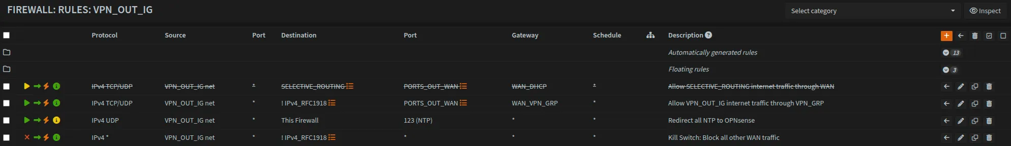
VPN_OUT_IG Rules
Navigate to Firewall → Rules → VPN_OUT_IG:
Optional: Selective Routing
| Action | Protocol | Source | Destination | Dest. Port | Gateway | Description |
|---|---|---|---|---|---|---|
| Pass | TCP/UDP | VPN_OUT_IG net | SELECTIVE_ROUTING | PORTS_OUT_WAN | - | Allow selected internet traffic through WAN |
The SELECTIVE_ROUTING alias is currently empty but can be populated with hosts that need to bypass VPN routing.
This rule is disabled and only necessary for some edge cases. For example, sites that block access through VPN.
Route VPN traffic through gateway group:
| Action | Protocol | Source | Destination | Dest. Port | Gateway | Description |
|---|---|---|---|---|---|---|
| Pass | TCP/UDP | VPN_OUT_IG net | !IPv4_RFC1918 | PORTS_OUT_WAN | WAN_VPN_GRP | Allow VPN_OUT_IG internet traffic through VPN_GRP |
Allow internet pings through VPN:
| Action | Protocol | Source | Destination | Dest. Port | Gateway | Description |
|---|---|---|---|---|---|---|
| Pass | ICMP | VPN_OUT_IG net | !IPv4_RFC1918 | * | WAN_VPN_GRP | Allow internet pings through VPN |
The TCP/UDP pass rule above does not match ICMP traffic (ping). Without this rule, internet pings bypass the VPN gateway and get caught by the kill switch. This rule ensures pings to external addresses are routed through the VPN tunnel like all other traffic.
NTP redirect to OPNsense:
| Action | Protocol | Source | Destination | Dest. Port | Gateway | Description |
|---|---|---|---|---|---|---|
| Pass | UDP | VPN_OUT_IG net | 10.0.0.1 | 123 (NTP) | * | Redirect all NTP to OPNsense |
Kill Switch (must be last rule):
| Action | Protocol | Source | Destination | Dest. Port | Gateway | Description |
|---|---|---|---|---|---|---|
| Block | * | VPN_OUT_IG net | !IPv4_RFC1918 | * | * | Kill Switch: Block all other WAN traffic |
The kill switch must be the last rule on VPN_OUT_IG. It blocks any internet-bound traffic that wasn’t matched by the VPN pass rules above (e.g., when VPN tunnels are down). Do not place this rule on WAN or as a floating rule - it won’t work correctly there.
Optional: LAN to ALL Networks
| Action | Protocol | Source | Destination | Description |
|---|---|---|---|---|
| Pass | TCP/UDP | Any | Any | Allow LAN access to ALL networks |
This rule should remain disabled but can be quickly enabled for troubleshooting when you need LAN devices to access all networks.
Optional: Cleanup for PORTS_OUT_LAN
When finalizing your configuration, consider removing the following from PORTS_OUT_LAN if you do not need them:
Port 53 (DNS): NAT redirect rules handle DNS routingPort 623 (IPMI): Only needed if you have hardware management interfaces (Dell iDRAC, HP iLO, etc.)Port 137 (NetBIOS): Used for network scanning; blocking can prevent unwanted discovery traffic. We do usePort 137for theFILE_SHARINGrule onSEC_LAN_IGto DMZ
AdGuard Home Setup
Installing AdGuard Home
AdGuard Home requires adding a third-party repository. SSH into OPNsense and run:
fetch -o /usr/local/etc/pkg/repos/mimugmail-single.conf https://www.routerperformance.net/mimugmail-single.confOnce the repository is added, navigate to System → Firmware → Plugins in the OPNsense UI and install os-AdGuardhome-maxit.
Enabling AdGuard Home
Navigate to Services → AdGuard and enable the service:
- ✓ Enable
- ✓ Primary DNS
If AdGuard doesn’t start properly or you need to verify the port configuration, SSH into OPNsense and manually edit the config:
nano /usr/local/AdGuardHome/AdGuardHome.yamlEnsure the DNS section specifies Port 53 (DNS):
dns:
  bind_hosts:
    - 10.0.0.1
  port: 53
Accessing AdGuard UI
Make sure you add port 3080 to your PORTS_OUT_LAN alias so that you can access AdGuard web interface.
Both LAN and SecWiFi can access AdGuard web interface.
Access the UI at: http://10.0.0.1:3080/
Configuring DNS Settings
Navigate to Settings → DNS Settings in the AdGuard UI.
Upstream DNS servers:
[/home.byteron.com/]10.0.0.1:5335
[/10.in-addr.arpa/]10.0.0.1:5335
10.0.0.1:5353
Fallback DNS servers:
10.0.0.1:5353Bootstrap DNS servers:
10.0.0.1:5353Private reverse DNS servers:
10.0.0.1:5335Click Test Upstream DNS to verify connectivity, then Save.
Update System DNS Configuration
Navigate to System → Settings → General and update the DNS configuration:
| Field | Value |
|---|---|
| DNS Server | 10.0.0.1 |
| Gateway | none |
Remove any other DNS entries to ensure all DNS queries go through AdGuard Home.
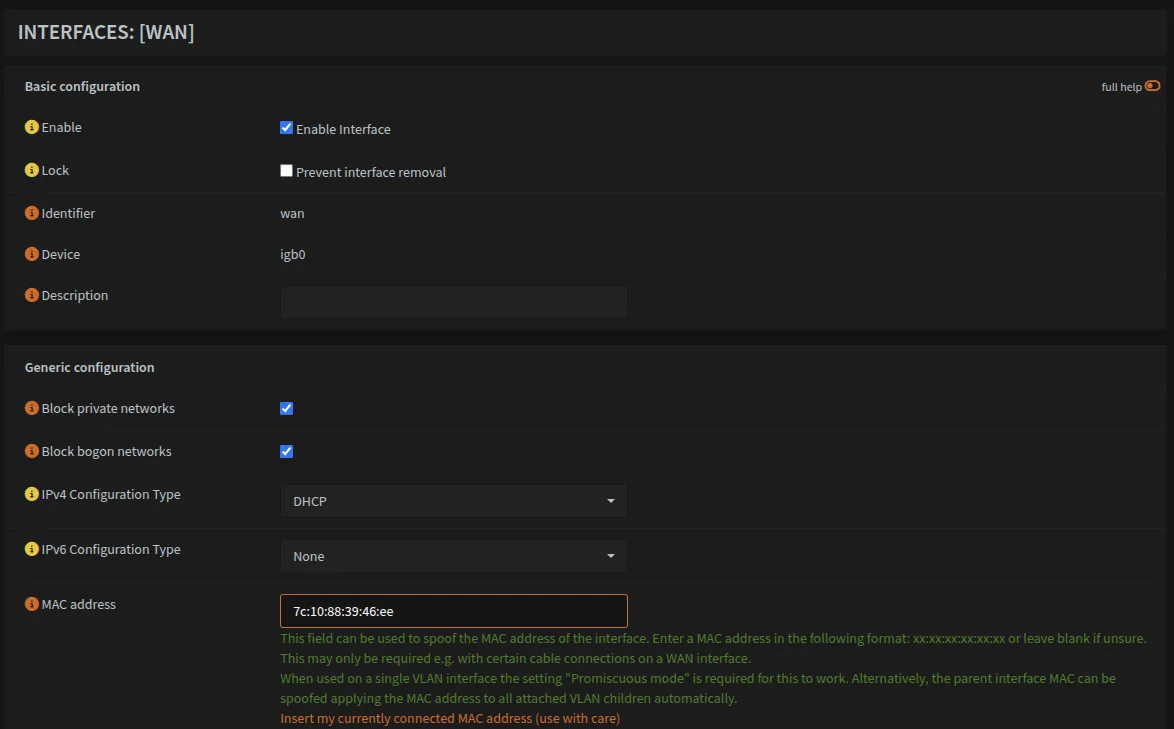
Optional: Retain WAN IP (MAC Spoofing)
If you’re migrating from another device and want to retain the same WAN IP from your ISP:
- Obtain the MAC address from your previous device
- Navigate to
Interfaces → WAN - Enter the MAC address in the MAC address field
- Save and restart the device
Your new device should now receive the same IP address from your ISP.
Interfaces → WAN should look like this:
Optional: Network Time Protocol (NTP)
Proper time synchronization is essential for security tools like SIEM and log correlation. This section ensures all devices sync time with OPNsense.
Configuring NTP Server
Navigate to Services → Network Time → General and configure:
- Select all interfaces (LAN, VLANs)
- Add upstream NTP servers (pick an option from pool.ntp.org that is in your region)
Force All Devices to Use OPNsense NTP
Create NAT redirect:
Navigate to Firewall → NAT → Port Forward (or Destination NAT in newer versions)
| Field | Value |
|---|---|
| Interface | VPN_OUT_IG |
| Protocol | UDP |
| Source | VPN_OUT_IG net |
| Destination | ! This Firewall |
| Dest Port | 123 (NTP) |
| Redirect to | 10.0.0.1:123 |
This transparently redirects all NTP traffic to OPNsense, ensuring consistent time across all devices.
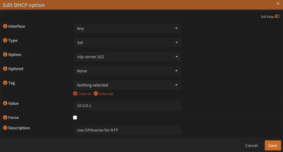
Configure DHCP NTP option:
Navigate to Services → DNSmasq DNS & DHCP → DHCP Options
Add DHCP option:
dhcp-option=42,10.0.0.1This tells DHCP clients to use 10.0.0.1 (OPNsense) as their NTP server.
Summary
Restart OPNsense to apply all changes.
Your setup now has:
- VPN routing for all traffic with automatic failover
- DNS filtering with AdGuard (all networks except
VLAN46) - Network segmentation and firewall rules
- Kill switch preventing WAN leaks
- NTP synchronization
- No DNS, WebRTC or ISP leaks
VLAN traffic, wireless VLAN access, and DMZ external access require additional switch and access point configuration covered in the guides below.
Next Steps
| Guide | Description | |
|---|---|---|
| VLAN Switch Configuration | Configure managed switches with IEEE 802.1Q VLAN tagging | Required |
| Testing Your Setup | Verify DNS, VPN tunnels, firewall rules and VLAN isolation | Recommended |
| Plex Remote Access | Configure Plex to bypass VPN routing | Optional |
| Local Domains & Reverse Proxy | Set up service.home.byteron.com style domains | Optional |
[references] ▸
- [1.1]
-
[1.2]
Schnerring: Baseline Guide with VPN — Primary inspiration for this guide
- [1.3]
- [2.1]
- [2.2]
- [2.3]
- [3.1]
- [3.2]
[changelog] ▸
- → Initial publication
Disclaimer
Use the information provided here at your own risk, but if you find errors or issues in this guide, leave a comment and I’ll try to address them ASAP.
Comments