TL;DR
Configure UniFi and Netgear managed switches to pass VLAN traffic for your OPNsense network. This guide covers a UniFi 24-port switch as the main distribution switch, Netgear GS108Ev3 for DMZ isolation, and UniFi WiFi APs broadcasting multiple SSIDs across VLANs.
Prerequisites:
- Completed OPNsense VLAN setup
- UniFi Network Application installed
- UniFi 24-port switch and Netgear GS108Ev3 managed switch
- UniFi WiFi access points (U6 Pro, UAP-AC-Lite, or similar)
What you’ll configure:
- UniFi switch trunk and access ports for VLANs
- Netgear GS108 dedicated DMZ switch with VLAN isolation
- UniFi WiFi APs with multiple SSIDs mapped to VLANs
Introduction
VLANs exist at layer 2, meaning they’re implemented on switches, not just routers. After configuring VLANs on OPNsense, you must configure your network switches to pass VLAN-tagged traffic correctly; otherwise, your VLANs won’t work regardless of how perfectly OPNsense is configured.
This guide complements the OPNsense VLAN setup described in the main configuration guide, covering switch-specific configuration for trunk ports, access ports, WiFi AP VLAN assignments, and DMZ isolation.
Trunk Ports: Carry multiple VLANs with tags preserved (802.1Q). Used for switch-to-switch or switch-to-router links.
Access Ports: Carry a single VLAN, stripping tags before delivering to end devices.
Native VLAN/PVID: Untagged traffic on a port is assigned to this VLAN.
- UniFi/Cisco: “Native VLAN”
- Netgear: “PVID” (Port VLAN ID)
Vendor-Specific Terminology:
- UniFi: Trunk = “All” or multiple networks | Access = single network
- Netgear: Trunk = tagged VLANs | Access = untagged VLAN membership
Network Topology Overview
Our Network Structure
graph TD
    Internet([Internet]) --> ISP[ISP Modem]
    ISP --> WAN[OPNsense igb0 WAN]
    WAN --> OPNsense[OPNsense Firewall]

    OPNsense -->|igb1 Trunk| Port23["UniFi Port 23
    LAN + VLAN40,42,44,46"]
    OPNsense -->|igb2 DMZ Only| Port24["UniFi Port 24
    Native: VLAN999, Tagged: VLAN10"]

    Port23 --> UniFi24[UniFi 24-Port Switch]
    Port24 --> UniFi24

    UniFi24 -->|Port 1
    Native: VL40, Tagged: 42,44,46| U6Pro["U6 Pro AP
    SSIDs: SecWiFi, IoT, Guest, GoatNET"]
    UniFi24 -->|Port 2
    Native: VL40, Tagged: 42,44,46| UALAC["UAP-AC-Lite
    SSIDs: SecWiFi, IoT, Guest, GoatNET"]
    UniFi24 -->|Port 10
    VLAN10| NetgearGS108[Netgear GS108]
    UniFi24 -->|Port 13
    LAN| MainPC[Main PC]
    UniFi24 -->|Port 15
    Trunk| FlexSwitch["USW Flex
    LAN + DMZ trunk"]

    NetgearGS108 -->|Ports 5-8
    VLAN10| DMZServers[DMZ Servers]

    FlexSwitch -->|Ports 2-5| FlexDevices[Extended Network Devices]

    class OPNsense danger
    class UniFi24 primary
    class NetgearGS108,FlexSwitch teal
    class Internet amber
VLAN Traffic Flow Through Switch
graph LR
    subgraph OPNsense
        igb1[igb1<br/>LAN interface]
        igb2[igb2<br/>vlan0.10 only]
    end

    subgraph "UniFi Switch Internal"
        P23[Port 23<br/>Native: LAN<br/>Tagged: 40,42,44,46]
        P24[Port 24<br/>Native: VL999<br/>Tagged: 10]
        Fabric{Switch<br/>Fabric}
        P1[Port 1<br/>Native: VL40<br/>Tagged: 42,44,46]
        P2[Port 2<br/>Native: VL40<br/>Tagged: 42,44,46]
        P10[Port 10<br/>Native: VL10]
        P13[Port 13<br/>Native: LAN<br/>Tagged: Allow All]
        P15[Port 15<br/>Native: LAN<br/>Tagged: Allow All]
    end

    subgraph Devices
        AP1[U6 Pro]
        AP2[UAP-AC-Lite]
        PC[Main PC]
        Netgear[Netgear GS108]
        Flex[USW Flex]
    end

    igb1 -->|Untagged LAN<br/>Tagged VL40,42,44,46| P23
    igb2 -->|Tagged VL10 only| P24
    P23 --> Fabric
    P24 --> Fabric
    Fabric --> P1
    Fabric --> P2
    Fabric --> P10
    Fabric --> P13
    Fabric --> P15
    P1 --> AP1
    P2 --> AP2
    P10 --> Netgear
    P13 --> PC
    P15 --> Flex

    class igb1,igb2 danger
    class Fabric primary
VLAN Traffic Flow:
- Trunk Ports (23, 24, 1, 2, 13, 15): Carry multiple VLANs with tags preserved
- Access Port (10): Carries only DMZ_VL10 untagged
VLAN Assignment Summary
| VLAN ID | Network Name | Purpose | Subnet | Physical Location |
|---|---|---|---|---|
| Default | LAN | Trusted wired devices | 10.0.0.0/24 | Port 13 (Main PC), Port 15 (USW Flex), Port 23 Native |
| VLAN10 | DMZ_VL10 | Public-facing servers | 10.0.10.0/24 | Port 24 Tagged → Port 10 → Netgear GS108 |
| VLAN40 | SECWIFI_VL40 | Secure WiFi | 10.0.40.0/24 | U6 Pro & UAP-AC-Lite (Native) |
| VLAN42 | IOT_VL42 | IoT WiFi devices | 10.0.42.0/24 | U6 Pro & UAP-AC-Lite (Tagged) |
| VLAN44 | GUEST_VL44 | Guest WiFi network | 10.0.44.0/24 | U6 Pro & UAP-AC-Lite (Tagged) |
| VLAN46 | GOATNET_VL46 | Unfiltered network | 10.0.46.0/24 | U6 Pro & UAP-AC-Lite (Tagged) |
| VLAN999 | BLACKHOLE_VL999 | Security (unused) | None | Port 24 Native (tags untagged as VL999) |
UniFi Switch Configuration
Configure the UniFi switch to implement the network topology and VLAN assignments described above.
Create VLANs in UniFi Controller
In Settings → Networks, create networks for each VLAN using these settings:
Common Settings (apply to ALL networks):
- Router: Third-party Gateway
- DHCP Mode: None
Create each network with these specific values:
| Network Name | VLAN ID | Gateway/Subnet | Purpose |
|---|---|---|---|
| LAN | Default (untagged) | 10.0.0.1/24 | Trusted wired devices (native on Ports 13, 15, 23) |
| DMZ_VL10 | 10 | 10.0.10.1/24 | Public-facing servers |
| SECWIFI_VL40 | 40 | 10.0.40.1/24 | Secure WiFi |
| IOT_VL42 | 42 | 10.0.42.1/24 | IoT WiFi devices |
| GUEST_VL44 | 44 | 10.0.44.1/24 | Guest WiFi |
| GOATNET_VL46 | 46 | 10.0.46.1/24 | Unfiltered network |
| BLACKHOLE_VL999 | 999 | (leave blank) | Security - black hole VLAN |

Use an unused VLAN VLAN999 as the native VLAN on trunk ports that should only carry tagged traffic. Any unexpected untagged frames get tagged as VLAN999 and discarded, preventing VLAN hopping attacks.
When to use Black Hole VLAN:
- Port 24 (DMZ Uplink): Carries only tagged
VLAN10. OPNsenseigb2has no native interface, so any untagged frames are security threats.
When to use Native LAN:
- Port 23 (OPNsense
igb1): Legitimate untagged LAN traffic from devices like the Main PC must reach OPNsense. - Port 15 (USW Flex): Devices at remote location need untagged LAN access, plus carries tagged VLANs like
DMZ_VL10for downstream switches.
Configure OPNsense Uplink Ports
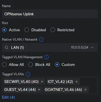
Port 23 - OPNsense igb1 (LAN + VLANs):
UniFi Devices → [Your Switch] → Ports → Port 23:
| Field | Value |
|---|---|
| Name | OPNsense Uplink |
| Native Network/VLAN | LAN |
| Tagged VLAN Management | Custom |
| Tagged VLANs | SECWIFI_VL40, IOT_VL42, GUEST_VL44, GOATNET_VL46 |
OPNsense igb1 handles untagged LAN traffic from devices like the Main PC (Port 13) and USW Flex
(Port 15). These untagged LAN frames must reach igb1, while the tagged WiFi VLANs (40, 42,
44, 46) pass through simultaneously.
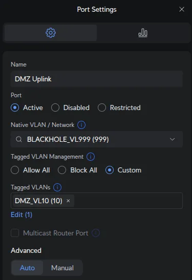
Port 24 - OPNsense igb2 (DMZ):
UniFi Devices → [Your Switch] → Ports → Port 24:
| Field | Value |
|---|---|
| Name | DMZ Uplink |
| Native Network/VLAN | BLACKHOLE_VL999 |
| Tagged VLAN Management | Custom |
| Tagged VLANs | DMZ_VL10 |
OPNsense igb2 has only vlan0.10 configured for tagged VLAN10. No native/untagged interface
exists on igb2. Setting native to VLAN999 ensures any untagged frames are discarded (security
best practice to prevent VLAN hopping attacks).
Create Port Profile for WiFi APs
Port profiles allow consistent configuration across multiple ports. We’ll create one profile for both WiFi access points.
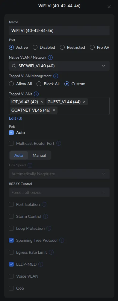
Settings → Profiles → Port Profile → Create New Profile:
| Field | Value |
|---|---|
| Profile Name | WiFi VL(40-42-44-46) |
| Native Network/VLAN | SECWIFI_VL40 |
| Tagged Networks | IOT_VL42, GUEST_VL44, GOATNET_VL46 |
AP management traffic uses the native VLAN SECWIFI_VL40. Since the UniFi Controller is on LAN, a
firewall rule allows UniFi devices on SECWIFI_VL40 to reach the controller. SecWiFi clients use
the native/untagged VLAN, while other SSIDs (IoT, Guest, GoatNET) use tagged VLANs 42, 44,
46.
Configure Access Ports and WiFi APs
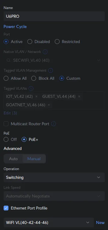
Ports 1 & 2 - WiFi Access Points:
UniFi Devices → [Your Switch] → Ports → Port 1:
| Field | Value |
|---|---|
| Port Profile | WiFi VL(40-42-44-46) |
Assign the same WiFi VL(40-42-44-46) profile to Port 2 (UAP-AC-Lite).
Both U6 Pro (Port 1) and UAP-AC-Lite (Port 2) broadcast all 4 SSIDs (SecWiFi, IoT_WiFi, Guest_WiFi, GoatNET) on different floors using identical VLAN assignments from the profile.
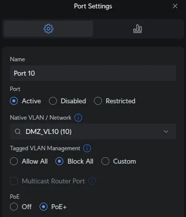
Port 10 - Netgear GS108 Uplink (DMZ):
UniFi Devices → [Your Switch] → Ports → Port 10:
| Field | Value |
|---|---|
| Native Network | DMZ_VL10 |
| Tagged VLAN Management | Block ALL |
Security isolation combined with proper VLAN handling. Here’s the traffic flow: - OPNsense sends
tagged VLAN10 to Port 24 - UniFi switch fabric routes VLAN10 to Port 10 - Port 10 sends
VLAN10 traffic untagged to Netgear because DMZ_VL10 is the native network - Netgear Port 1
receives untagged frames and re-tags them as VLAN10 via PVID 10 - Blocking all tagged VLANs on
Port 10 ensures no other network traffic can enter/exit this port, maintaining DMZ isolation
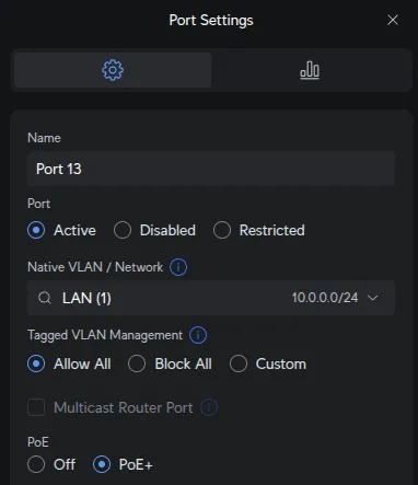
Port 13 - Main PC (LAN Access):
UniFi Devices → [Your Switch] → Ports → Port 13:
| Field | Value |
|---|---|
| Native Network | LAN |
| Tagged VLAN Management | Allow All |
Flexibility for future trunking if needed (e.g., running VMs on different VLANs). Currently used as LAN access port.
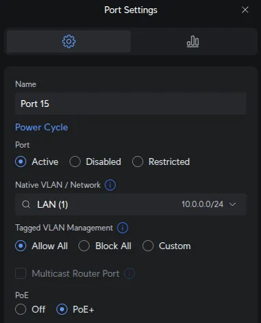
Port 15 - USW Flex Uplink (Trunk):
UniFi Devices → [Your Switch] → Ports → Port 15:
| Field | Value |
|---|---|
| Native Network | LAN |
| Tagged VLAN Management | Allow All |
Port 15 connects to USW Flex, which daisy-chains to a USW Flex Mini. The Flex Mini has a TV on
DMZ_VL10, requiring tagged VLAN10 to pass through Port 15 → Flex → Flex Mini. Native LAN
handles other devices at the remote location.
USW Flex Configuration
The USW Flex connected to Port 15 extends network access to a remote location.
Port Configuration:
- Port 1: Uplink to main switch Port 15 (receives LAN native + all tagged VLANs)
- Port 3: Trunk to USW Flex Mini (LAN native + tagged
DMZ_VL10) - Ports 2, 4-5: LAN access for local devices
The Flex receives all VLANs from Port 15, passes DMZ_VL10 downstream to the Flex Mini (which has a TV on DMZ_VL10), and provides LAN access to other devices at the remote location.
Netgear GS108 Configuration
With the UniFi switch configured, set up the Netgear GS108Ev3 to handle DMZ traffic isolation. The Netgear switch connects to UniFi Port 10, which receives DMZ VLAN10 from OPNsense igb2 via Port 24.
Configure Netgear Switch IP
Netgear switches ship with a factory static IP 192.168.0.239. To integrate it into your DMZ network, you’ll configure it to use DHCP with a static lease from OPNsense.
Step 1: Access switch via factory default IP:
- Connect your computer directly to the Netgear switch
- Set your computer to static IP:
192.168.0.2/24 - Browse to: http://192.168.0.239
- Login with default credentials:
admin/password
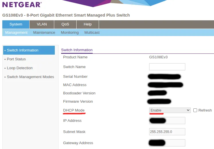
Step 2: Note the switch MAC address:
On the main screen (System → Management → Switch Information), note the switch MAC address. You’ll need this for the static DHCP lease.
Step 3: Configure static DHCP lease in OPNsense:
In OPNsense: Services → Dnsmasq DNS & DHCP → Hosts:
- MAC Address: [Your Netgear switch MAC address from Step 2]
- IP Address:
10.0.10.99 - Hostname:
netgear-dmz-switch - Domain: (leave blank or use your domain)
- Description: Netgear GS108Ev3 DMZ Switch
This ensures the switch gets 10.0.10.99 when it requests DHCP from DNSmasq.
Step 4: Enable DHCP mode on switch:
Back on the Netgear switch (System → Management → Switch Information):
- Check the DHCP Mode: Enable checkbox
- Click Apply
The switch will reboot and request an IP via DHCP from OPNsense, receiving 10.0.10.99 based on your static lease configuration.
Step 5: Access switch on DMZ network:
After the switch reboots:
- Reconnect your computer to the main network
- Access the switch at its new DHCP-assigned IP: http://10.0.10.99
- The switch now operates on your DMZ
VLAN10network
Create VLAN 10 (DMZ)
VLAN → 802.1Q → Advanced → VLAN Configuration → Add:
| Field | Value |
|---|---|
| VLAN ID | 10 |
Configure Port Memberships
VLAN → 802.1Q → Advanced → VLAN Membership:
VLAN 1 (Default - Unused):
Configure VLAN 1 to only include unused ports:
| Port | Membership | Purpose |
|---|---|---|
| 1 | Not checked (neither T nor U) | Uplink - only carries VLAN10, must NOT be in VLAN1 |
| 2-4 | Untagged (U) | Unused spare ports (factory default) |
| 5-8 | Not checked (neither T nor U) | DMZ servers - only in VLAN10, must NOT be in VLAN1 |
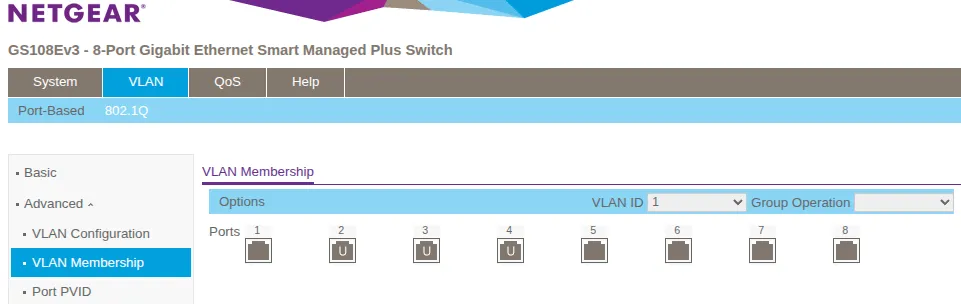
By default, ALL ports are members of VLAN1. You must explicitly remove Port 1 and Ports 5-8 from
VLAN1 by leaving them unchecked (neither T nor U). Leaving them in VLAN1 creates a security
risk - VLAN1 traffic could leak between the DMZ and management networks.
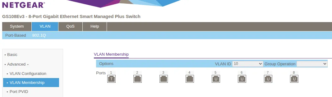
VLAN 10 (DMZ):
| Port | Membership Type | Purpose |
|---|---|---|
| 1 | Tagged (T) | Uplink to UniFi Port 10 (receives untagged, sends tagged) |
| 5 | Untagged (U) | DMZ Server 1 |
| 6 | Untagged (U) | DMZ Server 2 |
| 7 | Untagged (U) | DMZ Server 3 |
| 8 | Untagged (U) | DMZ Server 4 |
Select VLAN 10 from the dropdown menu. Set Port 1 as “Tagged” (T) for the uplink to UniFi Port 10. Set Ports 5-8 as “Untagged” (U) for DMZ servers.
Configure Port PVID (Native VLAN)
VLAN → 802.1Q → Advanced → Port PVID Configuration:
| Port | PVID | Purpose |
|---|---|---|
| 1 | 10 | Uplink to UniFi Port 10 (tags untagged incoming frames as VLAN10) |
| 2-4 | 1 | Unused (spare ports, left in default VLAN 1) |
| 5-8 | 10 | DMZ servers (tags untagged frames to VLAN10) |
What PVID does: PVID (Port VLAN ID) assigns untagged incoming frames to the specified VLAN - similar to “native VLAN” in Cisco terminology. Ports 5-8 need PVID 10 so DMZ servers’ untagged traffic gets tagged with VLAN10.
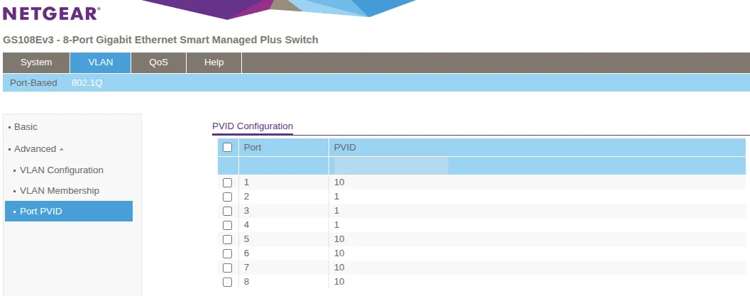
With this configuration, any device connected to ports 5-8 on the Netgear switch will automatically receive a DHCP address from the DMZ_VL10 subnet 10.0.10.0/24 via OPNsense DNSmasq.
WiFi Access Point Configuration
With the UniFi switch configured and WiFi APs connected to Ports 1 & 2, create wireless networks (SSIDs) and map them to VLANs. The Netgear switch handles only wired DMZ traffic and is not involved in WiFi configuration.
UniFi Access Points
UniFi APs are configured through the UniFi Controller and can broadcast multiple SSIDs, each on a different VLAN.
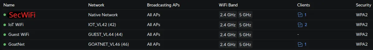
Create Wireless Networks (SSIDs)
In Settings → WiFi, create each SSID with these settings:
| SSID Name | Network | Security | Broadcasting APs | Notes |
|---|---|---|---|---|
| SecWiFi | Native Network | WPA2/WPA3 Personal | All APs | Strong password |
| IoT_WiFi | IOT_VL42 | WPA2 Personal | All APs | Device-compatible password |
| Guest_WiFi | GUEST_VL44 | WPA2 Personal | All APs | Optional: Enable Guest Portal |
| GoatNET | GOATNET_VL46 | WPA2/WPA3 Personal | All APs | Strong password |
Enable wireless meshing in each WiFi network’s settings by configuring Mesh Parents and Mesh Connect with both APs selected. This allows APs to wirelessly extend coverage.
Verification
Test your configuration systematically to ensure VLANs work correctly.
Step 1: Verify OPNsense VLAN Interfaces
On OPNsense:
ifconfig | grep vlanExpected output: All VLAN interfaces showing as UP:
vlan0.10: flags=8843<UP,BROADCAST,RUNNING,SIMPLEX,MULTICAST>
vlan0.40: flags=8843<UP,BROADCAST,RUNNING,SIMPLEX,MULTICAST>
vlan0.42: flags=8843<UP,BROADCAST,RUNNING,SIMPLEX,MULTICAST>
vlan0.44: flags=8843<UP,BROADCAST,RUNNING,SIMPLEX,MULTICAST>
vlan0.46: flags=8843<UP,BROADCAST,RUNNING,SIMPLEX,MULTICAST>
If any VLAN shows as DOWN, check OPNsense interface configuration.
Step 2: Test WiFi VLAN Assignment
Connect a device to each WiFi network and verify it receives the correct subnet:
ip addr show | grep inetExpected results:
- SecWiFi:
10.0.40.x(e.g.,10.0.40.105) - IoT_WiFi:
10.0.42.x(e.g.,10.0.42.112) - Guest_WiFi:
10.0.44.x(e.g.,10.0.44.101) - GoatNET:
10.0.46.x(e.g.,10.0.46.108)
If wrong subnet: Check SSID→Network assignment in UniFi WiFi settings and port profile on switch ports 1 & 2.
Step 3: Verify VLAN Isolation
From a device on SECWIFI_VL40, attempt to reach another VLAN:
ping 10.0.42.1Expected: No response (OPNsense firewall rules block inter-VLAN traffic by default).
If ping succeeds: Check OPNsense firewall rules - VLANs should not be able to reach each other unless explicitly allowed.
Step 4: Test Internet Access
From devices on each VLAN:
ping 1.1.1.1
curl -I https://www.google.com
Expected: Both should succeed on all VLANs.
If fails: Check OPNsense outbound NAT rules and firewall allow rules for internet access.
Step 5: Verify DMZ Isolation
From a DMZ device (connected to Netgear):
# Should get IP from DMZ subnet
ip addr  # Expected: 10.0.10.x

# Should reach internet
ping 1.1.1.1  # Expected: Success

# Should NOT reach LAN
ping 10.0.0.1  # Expected: Timeout (firewall blocks DMZ→LAN)
From LAN device:
# LAN can reach DMZ (SEC_LAN_IG ICMP intranet ping rule allows LAN→DMZ)
ping 10.0.10.1  # Expected: Success
Notes
This post is intended to be used in conjunction with OPNsense VLAN setup
[references] ▸
-
[1.1]
Building a Secure Home Network with OPNsense — Complete OPNsense VLAN configuration
-
[1.2]
Testing Your OPNsense Setup — Verification procedures
-
[1.3]
Plex Remote Access Through OPNsense — Selective routing configuration
-
[2.1]
UniFi Network Application — Official UniFi documentation
-
[2.2]
Netgear GS108Ev3 Manual — Switch configuration manual
-
[3.1]
Switch Port VLAN Assignment (Trunk & Access Ports) — UniFi VLAN configuration and trunk port behavior
-
[3.2]
How to Configure VLANs on NETGEAR Managed Switches — NETGEAR VLAN setup guide
-
[3.3]
VLAN Membership vs PVID — Understanding PVID and tagged/untagged ports
[changelog] ▸
- → Added configuration screenshots
- → Fixed technical inaccuracies in traffic flow descriptions
- → Improved table formatting and callout usage
- → Initial publication
Disclaimer
Use the information provided here at your own risk, but if you find errors or issues in this guide, leave a comment and I’ll try to address them ASAP.
Comments